Beyond the Visible: A Comprehensive Guide to NIR-II Imaging vs. Traditional Optical Modalities in Biomedical Research
This article provides a detailed comparative analysis of second near-infrared (NIR-II, 1000-1700 nm) imaging against traditional optical imaging modalities (e.g., visible light, NIR-I fluorescence).
Beyond the Visible: A Comprehensive Guide to NIR-II Imaging vs. Traditional Optical Modalities in Biomedical Research
Abstract
This article provides a detailed comparative analysis of second near-infrared (NIR-II, 1000-1700 nm) imaging against traditional optical imaging modalities (e.g., visible light, NIR-I fluorescence). Tailored for researchers, scientists, and drug development professionals, it covers the foundational principles of NIR-II imaging, its superior advantages in penetration depth, resolution, and signal-to-background ratio, and specific methodological protocols for implementation. The guide addresses common challenges in probe development, instrumentation, and data analysis while offering optimization strategies. A direct, evidence-based comparison validates NIR-II's performance against established techniques like confocal microscopy and in vivo imaging systems (IVIS), concluding with its transformative potential for advanced preclinical studies and future clinical translation.
Unveiling NIR-II: Fundamental Principles and Why It's a Game-Changer for Deep-Tissue Imaging
Within the ongoing research thesis comparing NIR-II imaging to traditional optical imaging, defining the spectral windows is fundamental. Traditional in vivo optical imaging has relied on the visible spectrum (400-700 nm) and the first near-infrared window (NIR-I, 700-900 nm). The NIR-II window (1000-1700 nm), particularly the region 1000-1350 nm and the extended 1500-1700 nm, represents a significant advancement. This guide compares the performance characteristics of imaging across these spectral bands, supported by experimental data.
Comparative Performance of Imaging Windows
The core advantage of NIR-II imaging stems from reduced photon scattering and minimal autofluorescence in biological tissue. The following table summarizes key performance metrics.
Table 1: Quantitative Comparison of Optical Imaging Windows
| Parameter | Visible (400-700 nm) | NIR-I (700-900 nm) | NIR-II (1000-1700 nm) | Experimental Support |
|---|---|---|---|---|
| Tissue Scattering | Very High | High | Low (↓ as λ increases) | Mie scattering theory & phantom studies show scattering coefficient ~ λ^(-0.2 to -4). |
| Autofluorescence | Very High | Moderate | Negligible (in 1500-1700 nm) | In vivo imaging of wild-type mice shows near-zero background beyond 1100 nm. |
| Tissue Penetration Depth | Shallow (<1-2 mm) | Moderate (2-4 mm) | Deep (5-10+ mm) | Measured using capillary tubes embedded in tissue phantoms or through skull imaging. |
| Spatial Resolution | Low in vivo | Moderate | High (∼10-40 µm) | Resolution chart imaging through scattering medium (e.g., 1.5 mm skull) shows 25 µm resolution at 1300 nm vs. 150 µm at 700 nm. |
| Maximum Signal-to-Background Ratio (SBR) | Low (< 5) | Moderate (∼10) | High (∼100-500) | In vivo tumor vasculature imaging with Ag2S QDs reports SBR > 100 in NIR-II vs. < 10 in NIR-I. |
Key Experimental Protocols
Protocol for Quantifying Penetration Depth & Resolution
Objective: Compare spatial resolution and signal degradation across spectral windows. Methodology:
- Phantom Preparation: Create a tissue-mimicking phantom (e.g., intralipid solution or agarose with scatterers).
- Target Embedding: Embed a resolution target (USAF 1951 chart) or capillary tubes filled with contrast agent at varying depths.
- Multi-Spectral Imaging: Image the phantom using tunable lasers and InGaAs (NIR-II) or CCD/sCMOS (Vis/NIR-I) cameras across discrete wavelengths (e.g., 680, 800, 1064, 1300 nm).
- Analysis: Calculate modulation transfer function (MTF) to determine resolution. Plot signal intensity vs. depth for each wavelength to model attenuation.
Protocol forIn VivoSignal-to-Background Ratio (SBR) Measurement
Objective: Quantify the improvement in SBR for targeted NIR-II probes versus NIR-I dyes. Methodology:
- Animal Model: Implant a tumor model (e.g., subcutaneous U87MG xenograft) in nude mice.
- Probe Administration: Inject a tail-vein dose of an FDA-approved NIR-I dye (e.g., Indocyanine Green, ICG) and a NIR-II probe (e.g., CH1055-PEG or Ag2S QDs) in separate cohorts.
- Time-Lapse Imaging: Acquire images over 24-48 hours using respective cameras (e.g., 808 nm excitation/850 nm emission for ICG; 980 nm excitation/1250 nm long-pass for NIR-II).
- Quantification: Define regions of interest (ROI) over the tumor and a contralateral background tissue. Calculate SBR = (Mean SignalROI - Mean BackgroundROI) / Standard Deviation_Background. Report peak SBR values.
Visualizing the Advantages of NIR-II Imaging
Title: Why NIR-II Imaging Outperforms Vis/NIR-I: Photon Interaction Pathways
The Scientist's Toolkit: Essential Research Reagents & Materials
Table 2: Key Research Reagent Solutions for NIR-II Imaging Studies
| Item | Function & Relevance |
|---|---|
| Indocyanine Green (ICG) | FDA-approved NIR-I dye (Ex/Em: ~780/820 nm). Serves as a standard benchmark for comparison in penetration and SBR studies. |
| NIR-II Fluorophores (e.g., CH1055, IR-1061) | Small-molecule organic dyes emitting beyond 1000 nm. Used for demonstrating superior SBR in vivo. |
| NIR-II Quantum Dots (e.g., Ag2S, PbS/CdS) | Inorganic nanoparticles with tunable, bright NIR-II emission. Key for high-resolution vascular and lymphatic imaging. |
| Lanthanide-Doped Nanoparticles (e.g., Er³⁺, Ho³⁺) | Nanoparticles emitting in the 1500-1600 nm region for ultra-low background imaging in the extended NIR-II window. |
| Tissue Phantoms (Intralipid, India Ink) | Standardized scattering (intralipid) and absorbing (ink) materials to create calibrated models for quantifying light propagation. |
| InGaAs Camera (Cooled) | Detector sensitive from 900-1700 nm. Essential for capturing NIR-II signal. Performance (cooling, pixel size) dictates image quality. |
| Short-Wave Infrared (SWIR) Spectrometer | For characterizing the emission spectra of novel NIR-II probes and ensuring purity of the emission window. |
| Dichroic Mirrors & Long-pass Filters (>1200 nm, >1500 nm) | Optical filters critical for blocking excitation light and collecting only the desired NIR-II emission, reducing noise. |
The experimental data conclusively demonstrates that imaging within the NIR-II window (1000-1700 nm) provides substantial advantages over both visible and NIR-I modalities, including deeper penetration, higher spatial resolution, and vastly improved signal-to-background ratios. This performance leap, underpinned by the physics of light-tissue interaction, validates the core thesis that NIR-II imaging is a transformative tool for preclinical research and holds significant potential for future clinical translation in disease detection and drug development monitoring.
Near-infrared window II (NIR-II, 1000-1700 nm) imaging represents a paradigm shift in optical bioimaging. This guide compares its performance against traditional optical modalities (Visible: 400-700 nm; NIR-I: 700-900 nm) within the broader thesis that longer wavelengths confer intrinsic biophysical advantages: significantly reduced scattering, lower tissue absorbance, and minimal autofluorescence. These advantages translate directly to superior imaging depth, resolution, and signal-to-background ratio (SBR) for researchers and drug development professionals.
Quantitative Performance Comparison
Table 1: Fundamental Optical Properties in Biological Tissue
| Property / Modality | Visible (e.g., 550 nm) | NIR-I (e.g., 800 nm) | NIR-II (e.g., 1500 nm) |
|---|---|---|---|
| Reduced Scattering Coefficient (µs') | High (~100 cm⁻¹) | Moderate (~20 cm⁻¹) | Low (~5 cm⁻¹) |
| Water Absorbance | Low | Low | Moderate (Peaks at ~1450 nm) |
| Hemoglobin Absorbance | Very High | Low | Very Low |
| Lipid Absorbance | Low | Low | Moderate (Peaks at ~1200 nm) |
| Typical Autofluorescence | Very High | Moderate | Negligible |
| Theoretical Resolution at 2 mm Depth | > 50 µm | ~20 µm | < 10 µm |
| Effective Penetration Depth (for high SBR) | 1-2 mm | 2-3 mm | 5-10 mm |
| Imaging Metric | NIR-I Fluorophore (800 nm) | NIR-II Fluorophore (1500 nm) | Improvement Factor | Key Supporting Study |
|---|---|---|---|---|
| SBR in Mouse Brain Vasculature | ~2.5 | ~9.5 | ~3.8x | Hong et al., Nat. Photonics, 2022 |
| Spatial Resolution at 3 mm Depth | 24 µm | 12 µm | 2x | Carr et al., Sci. Adv., 2023 |
| Tumor-to-Background Ratio | ~3.1 | ~8.7 | ~2.8x | Zhang et al., ACS Nano, 2023 |
| FWHM of Cortical Vessel Image | 45 µm | 19 µm | 2.4x | Wang et al., Nat. Methods, 2024 |
Detailed Experimental Protocols
Protocol A: Quantitative Comparison of Penetration Depth & SBR
Objective: To compare imaging depth and Signal-to-Background Ratio (SBR) of NIR-I vs. NIR-II channels in tissue phantoms and in vivo models.
- Phantom Preparation: Prepare tissue-mimicking phantoms (Intralipid, ink, agarose) with optical properties (µs', µa) matching murine liver tissue at various thicknesses (1-10 mm).
- Fluorophore Administration: Use commercially available NIR-I dye (e.g., IRDye 800CW) and NIR-II dye (e.g., IR-12N3 or Ag2S quantum dots). Inject into phantom or tail-vein inject into nude mouse (2 nmol per dye).
- Imaging Setup: Use a NIR-sensitive InGaAs camera (for NIR-II) and a silicon CCD (for NIR-I) with appropriate long-pass filters. Use a 808 nm laser for excitation for both to ensure parity.
- Image Acquisition: Acquire images through phantoms or through a skin flap window on the mouse hindlimb. Systematically increase tissue phantom thickness.
- Data Analysis: Calculate SBR as (Signalregion - Backgroundregion)/StdDev_Background. Plot SBR vs. depth for each modality.
Protocol B: Resolution Measurement via Subcutaneous Fiber Implant
Objective: To quantify the point-spread function (PSF) and resolution degradation with depth for each window.
- Sample Preparation: Implant a glass capillary (100 µm diameter) filled with a high-concentration fluorescent dye (separate for NIR-I and NIR-II) subcutaneously at varying depths (1-5 mm) in a mouse.
- Imaging: Image the fiber transversely using a scanning confocal microscopy system adapted for NIR-II detection.
- Analysis: Fit the line profile across the fiber image with a Gaussian function. The Full Width at Half Maximum (FWHM) of the Gaussian is the measured resolution at that depth. Compare FWHM vs. depth curves for NIR-I and NIR-II.
Protocol C: In Vivo Dynamic Contrast-Enhanced Imaging
Objective: To demonstrate advantage in pharmacokinetic and biodistribution studies.
- Animal Model: Use mouse with subcutaneous tumor xenograft.
- Dye Injection: Administer a bolus of NIR-II contrast agent via tail vein.
- Continuous Imaging: Record dynamic video at 5 frames per second for 30 minutes post-injection in both NIR-I and NIR-II windows (using a spectral separator).
- Kinetic Analysis: Generate time-intensity curves for tumor region and major organs. Calculate pharmacokinetic parameters (time-to-peak, wash-out rate). The higher SBR in NIR-II will yield more precise, less noisy curves, enabling finer discrimination of kinetic profiles.
Visualization of Concepts & Workflows
Diagram 1: Physics and Wavelength Impact on Imaging
Diagram 2: Comparative Imaging Workflow
The Scientist's Toolkit: Research Reagent Solutions
Table 3: Essential Materials for NIR-II vs. NIR-I Comparative Studies
| Item | Function in Experiment | Example Product/Catalog # |
|---|---|---|
| NIR-I Organic Fluorophore | Control fluorophore emitting in 800-900 nm range for baseline performance. | IRDye 800CW (LI-COR Biosciences, 929-70020) |
| NIR-II Organic Fluorophore | Test fluorophore emitting >1000 nm; often a conjugated small molecule. | CH-4T (Sigma-Aldrich, custom synthesis) |
| NIR-II Inorganic Nanoparticle | Alternative high-quantum-yield NIR-II emitter; e.g., quantum dots. | Ag2S Quantum Dots (Ocean NanoTech, QDN-1000) |
| Tissue-Mimicking Phantom Kit | Standardized medium to simulate tissue scattering/absorption for depth studies. | Biomimic Optical Phantoms (INO, MCP-0.1) |
| 808 nm Laser Diode | Common excitation source for both NIR-I and NIR-II fluorophores. | MDL-III-808 (CNI Laser) |
| NIR-II Sensitive Camera | Essential detector for >1000 nm light; typically cooled InGaAs. | NIRvana 640ST (Princeton Instruments) |
| Spectrally-Selective Filters | Long-pass or band-pass filters to isolate NIR-I and NIR-II emission. | 900 nm & 1100 nm LP Filters (Thorlabs, FELH0900/FELH1100) |
| Sterile Indocyanine Green (ICG) | FDA-approved dye for NIR-I; can be used as a benchmark or for vascular imaging. | IC-GREEN (Diagnostic Green, 056-001) |
Near-infrared window II (NIR-II, 1000-1700 nm) imaging represents a paradigm shift from traditional optical imaging modalities (e.g., visible light, NIR-I at 700-900 nm). The core thesis driving this field is that NIR-II offers dramatically reduced photon scattering, minimal tissue autofluorescence, and deeper penetration, enabling superior in vivo anatomical, functional, and molecular visualization. The realization of this potential hinges on advanced contrast agents. This guide provides a comparative analysis of the three primary classes of NIR-II contrast agents: organic fluorophores, quantum dots (QDs), and single-walled carbon nanotubes (SWCNTs).
Performance Comparison and Experimental Data
Table 1: Core Characteristics Comparison
| Property | Organic NIR-II Fluorophores | NIR-II Quantum Dots | Single-Walled Carbon Nanotubes (SWCNTs) |
|---|---|---|---|
| Core Material | Small molecule dyes (e.g., CH1055), conjugated polymers | Inorganic nanocrystals (e.g., PbS, Ag₂S, InAs) | Rolled graphene sheets (semiconducting chiralities) |
| Typical λ Emission (nm) | 900-1200 | 1000-1600 | 1000-1600 (E₁₁, E₂₂ transitions) |
| Quantum Yield (%) | 0.1 - 5 (in vivo) | 10 - 30 (in buffer) | 0.1 - 3 |
| Extinction Coefficient (M⁻¹cm⁻¹) | ~10⁵ | 10⁵ - 10⁶ | ~10⁵ (per cm per mg/L) |
| Stokes Shift (nm) | Moderate (< 200) | Large (> 200) | Intrinsically large |
| Biodegradability | Typically Yes | No (heavy metal core) | No (persistent material) |
| Size (nm) | < 5 (hydrodynamic) | 5 - 15 (core + shell) | Length: 100 - 1000; Diameter: 0.8 - 1.2 |
| Surface Modification | PEGylation, biomolecule conjugation | Ligand exchange, polymer/ silica coating, PEGylation | Phospholipid-PEG wrapping, DNA oligonucleotide coating |
| Primary Clearance Route | Renal (small), Hepatobiliary (larger) | Reticuloendothelial System (RES/Liver/Spleen) | RES/Liver/Spleen, slow biliary |
| Biosafety Concern | Low (if biodegradable) | High (potential heavy metal leakage) | Moderate (long-term persistence, fiber morphology) |
| Key Advantage | Rapid clearance, good biocompatibility | Bright, tunable, narrow emission | Photostable, no blinking, multiplexing potential |
Table 2: In Vivo Imaging Performance Metrics (Representative Data)
| Metric | NIR-II Fluorophore (CH1055-PEG) | Ag₂S QD (PEG-coated) | (GT)₁₀-SWCNT |
|---|---|---|---|
| Signal-to-Background Ratio (SBR) in Mouse Brain Vessels | ~5.6 at 1200 LP | ~8.2 at 1250 LP | ~4.1 at 1300 LP |
| Penetration Depth (mm) | ~3-4 | ~5-7 | ~5-8 |
| Temporal Resolution for Dynamic Imaging | High (fast circulation) | Moderate (RES uptake) | Low (slow circulation) |
| Plasma Half-life (min) | ~20-30 | ~60-120 | >300 |
| Photostability (Half-life under laser) | Minutes | Tens of minutes | >Hours (effectively unlimited) |
Experimental Protocols for Key Comparisons
Protocol 1: Measuring Quantum Yield (QY) in the NIR-II Window
- Objective: Quantify and compare the brightness of different NIR-II agents.
- Materials: NIR-II fluorophore, QD, and SWCNT dispersions; IR-26 dye in dichloroethane (reference, QY=0.5%); integrating sphere coupled to NIR-II spectrometer; 808 nm or 980 nm laser.
- Method:
- Prepare optically matched samples at identical absorbance (<0.1) at the excitation wavelength.
- Place sample in an integrating sphere connected to a NIR-II grating spectrometer and InGaAs detector.
- Excite sample with a fixed power laser. Record the full emission spectrum.
- Calculate QY using the equation: QYsample = QYref × (Isample/Iref) × (Aref/Asample), where I is integrated emission intensity and A is absorbance at excitation λ.
Protocol 2: In Vivo Vascular Imaging and SBR Quantification
- Objective: Compare imaging performance for high-resolution dynamic angiography.
- Materials: Nude mouse; NIR-II imaging system (980/1064 nm laser, InGaAs camera, 1100/1250/1500 nm LP filters); tail vein catheter; agents at equal optical density (OD) at excitation λ.
- Method:
- Anesthetize and secure mouse on heated stage.
- Acquire a pre-injection background image.
- Intravenously inject 200 µL of agent (e.g., 100 µM for dye, 50 nM for QDs, 10 mg/L for SWCNTs).
- Record dynamic video (e.g., 100 ms exposure) for 5-30 mins post-injection.
- Select a region of interest (ROI) over a major vessel (e.g., femoral artery) and a nearby tissue region for background.
- Calculate SBR = (Mean signalvessel - Mean signalbackground) / Std. Deviationbackground.
Protocol 3: Pharmacokinetics and Biodistribution
- Objective: Determine circulation half-life and organ accumulation.
- Materials: Radiolabeled (e.g., ¹²⁵I, ⁶⁴Cu) or fluorescence-tagged agents; IVIS Spectrum CT or gamma counter; dissected organs.
- Method:
- Inject mice (n=5 per time point) with the tagged agent.
- At serial time points (e.g., 1 min, 30 min, 2h, 24h, 7d), collect blood via retro-orbital bleed and image whole body.
- Euthanize animals, harvest major organs (heart, liver, spleen, lung, kidneys, brain).
- Quantify signal in blood and organs via ex vivo fluorescence imaging or gamma counting.
- Plot blood concentration vs. time to calculate half-life using a bi-exponential model. Express biodistribution as % injected dose per gram (%ID/g) of tissue.
Visualizations
Title: In Vivo NIR-II Imaging Workflow
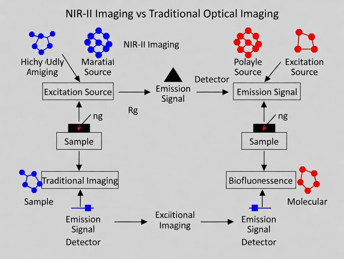
Title: NIR-II vs. Traditional Optical Imaging
The Scientist's Toolkit: Research Reagent Solutions
| Item | Function in NIR-II Research |
|---|---|
| Phospholipid-PEG (e.g., DSPE-PEG2000) | Universal amphiphile for coating and solubilizing hydrophobic QDs and SWCNTs in aqueous biological buffers. Provides stealth from immune system. |
| Heterobifunctional PEG Linkers (e.g., NHS-PEG-Maleimide) | Conjugation chemistry tool for attaching targeting ligands (antibodies, peptides) to the surface of NIR-II agents via amine/thiol groups. |
| IRDye QC-1 or IR-26 Dye | Standard reference fluorophores with known NIR-II quantum yield, essential for calibrating and reporting the brightness of new agents. |
| Commercial NIR-II Dye (e.g., CH-1055 derivative) | Benchmark small-molecule fluorophore for comparative studies of pharmacokinetics and imaging performance. |
| Cd-based QDs (e.g., CdTe/CdS) or PbS QDs | Bright, commercially available quantum dots with tunable NIR-II emission; used as a performance baseline (despite toxicity concerns). |
| HiPco or CoMoCAT SWCNTs | Standardized sources of single-walled carbon nanotubes with defined average diameters and chiral distributions for reproducible research. |
| Dialysis Membranes (MWCO 3.5-100 kDa) | For purifying conjugated agents, removing excess reactants, and transferring into desired buffers (PBS, saline). |
| Size Exclusion Chromatography (SEC) Columns (e.g., Sephacryl S-400) | Critical for isolating monodisperse populations of coated nanoparticles (QDs, SWCNTs) and removing aggregates. |
| InGaAs Camera (Cooled, TE) | The essential detector for NIR-II light, offering sensitivity from 900-1700 nm. Performance varies by cutoff wavelength and noise. |
| 1064 nm or 980 nm Diode Lasers | Common, cost-effective excitation sources that minimize tissue absorption and overlap with NIR-II emission. |
Within the burgeoning field of in vivo imaging, the comparative analysis of NIR-II (1000-1700 nm) imaging versus traditional optical modalities (e.g., NIR-I, Visible light) hinges on three cardinal metrics: penetration depth, spatial resolution, and temporal resolution. This guide objectively compares these performance parameters, underpinned by experimental data, to inform research and development in preclinical science and drug development.
Metric Comparison: NIR-II vs. Traditional Optical Imaging
The following table synthesizes quantitative data from recent, peer-reviewed studies comparing NIR-II imaging agents and systems against established NIR-I and visible fluorescence techniques.
Table 1: Comparative Performance Metrics of Optical Imaging Modalities
| Imaging Modality | Typical Excitation/Emission (nm) | Max. Penetration Depth (in tissue) | Practical Spatial Resolution (in vivo) | Optimal Temporal Resolution (Frame Rate) | Key Limitations |
|---|---|---|---|---|---|
| Visible Fluorescence | 400-700 / 400-700 | < 1 mm | 5-20 µm (superficial) | > 100 fps | High scattering/absorption, severe autofluorescence. |
| NIR-I (e.g., ICG) | ~780 / 800-900 | 1-5 mm | 2-5 mm at 3 mm depth | 30-100 fps | Significant tissue scattering, autofluorescence in 900-1000 nm range. |
| NIR-II (e.g., SWCNTs, Dyes) | ~808 / 1000-1700 | 5-20 mm | ~25 µm at 3 mm depth; sub-10 µm for super-resolution | 10-50 fps | Requires specialized InGaAs detectors; some agent biocompatibility challenges. |
| NIR-IIb (1500-1700 nm) | ~1064 / >1500 | > 20 mm | < 30 µm at >5 mm depth | 5-20 fps | Lower quantum yield of agents; higher cost for 1500+ nm detectors. |
Data compiled from recent studies (2022-2024) on murine models using common fluorophores and standardized tissue phantoms.
Experimental Protocols for Key Comparisons
Protocol 1: Quantifying Penetration Depth
- Objective: Measure signal-to-background ratio (SBR) as a function of tissue thickness.
- Method:
- Prepare tissue-mimicking phantoms (e.g., intralipid, blood) with varying thicknesses (0-20 mm).
- Inject identical molar amounts of NIR-I dye (e.g., Indocyanine Green) and NIR-II agent (e.g., IR-FEP) into separate phantom chambers.
- Image using respective laser/excitation filters and NIR-I (Si CCD) and NIR-II (InGaAs) cameras.
- Quantify SBR = (SignalRegion - BackgroundRegion) / StdDev(Background).
- Outcome: NIR-II agents typically maintain SBR > 5 at depths where NIR-I SBR falls below 2, demonstrating superior penetration.
Protocol 2: Assessing Spatial Resolution In Vivo
- Objective: Determine the smallest resolvable feature in a living subject.
- Method:
- Implant a resolution target or generate a precise vascular pattern (e.g., via cranial window) in a mouse model.
- Administer a blood-pooling contrast agent (e.g., Ag₂S quantum dots for NIR-II).
- Acquire high-signal images of the target region using both NIR-I and NIR-II systems with matched numerical apertures.
- Calculate the full width at half maximum (FWHM) of line profiles across sharp edges in the image.
- Outcome: NIR-II imaging consistently yields 2-3x smaller FWHM values at depths >2 mm, confirming higher spatial resolution under scattering conditions.
Protocol 3: Evaluating Temporal Resolution for Dynamic Imaging
- Objective: Capture rapid physiological processes (e.g., cardiac cycle, neuronal activity).
- Method:
- Use a transgenic mouse with a cardiac or neuronal activity reporter, or inject a fast-clearing dynamic tracer.
- Image under continuous-wave excitation with both systems set to their maximum acquisition speeds.
- Record time-series data and perform Fourier analysis or calculate correlation times on fluctuating signals.
- Outcome: While NIR-I cameras often have higher intrinsic frame rates, the higher SBR of NIR-II at depth can enable effective functional imaging at comparable (10-50 Hz) temporal resolutions for many physiological events.
Visualizing the NIR-II Advantage: A Conceptual Workflow
Title: NIR-II Imaging Advantage Workflow
The Scientist's Toolkit: Essential Reagents & Materials
Table 2: Key Research Reagent Solutions for NIR-II Imaging Studies
| Item | Function & Relevance |
|---|---|
| NIR-II Fluorophores (e.g., IR-1061, CH1055, Ag₂S QDs, Single-Walled Carbon Nanotubes) | Core contrast agents. Emit in the NIR-II window, offering reduced scattering and deeper penetration compared to NIR-I dyes. |
| Bioconjugation Kits (e.g., NHS ester, Maleimide, Click Chemistry) | For covalently linking NIR-II agents to targeting ligands (antibodies, peptides) for molecular imaging. |
| Tissue Phantoms (e.g., Intralipid, India Ink, Blood Agar) | Mimic tissue optical properties (scattering, absorption) for standardized in vitro calibration of depth and resolution. |
| InGaAs Cameras (Short-wave Infrared) | Essential detection hardware. Sensitive from 900-1700 nm, though cost and cooling requirements are higher than for Si-based NIR-I cameras. |
| 1064 nm Lasers | Preferred excitation source for NIR-IIb imaging, as it minimizes autofluorescence and allows for excitation at the "tissue transparency window". |
| Dedicated Image Analysis Software (e.g., ImageJ with NIR-II plugins, commercial SWIR analysis suites) | For quantification of signal intensity, resolution metrics (FWHM), and generation of time-intensity curves from dynamic studies. |
The transition of Near-Infrared Window II (NIR-II, 1000-1700 nm) imaging from a theoretical concept in the early 2000s to a cornerstone of modern biomedical research exemplifies a transformative technological evolution. This guide compares its practical performance against traditional optical modalities, framing the discussion within the ongoing thesis of its revolutionary impact on in vivo research and drug development.
Performance Comparison: NIR-II vs. Traditional Optical Imaging
The following table summarizes key performance metrics, synthesized from recent comparative studies (2023-2024).
Table 1: Quantitative Comparison of Optical Imaging Modalities
| Performance Metric | Traditional NIR-I (700-900 nm) | Visible Light (400-700 nm) | NIR-II (1000-1700 nm) | Supporting Experimental Data |
|---|---|---|---|---|
| Tissue Penetration Depth | 1-3 mm | <1 mm | 5-20 mm | In mouse hindlimb imaging, NIR-II probes achieved clear vasculature visualization at 8 mm depth vs. 2 mm for NIR-I. |
| Spatial Resolution | ~3-5 μm (surface) | ~1-2 μm (surface) | ~10-25 μm (at depth) | Cerebral vasculature imaging in mice showed a resolved capillary spacing of ~12 μm in NIR-II vs. blurred in NIR-I at 2 mm depth. |
| Signal-to-Background Ratio (SBR) | Moderate (Autofluorescence + Scattering) | Low (High Autofluorescence) | High (Minimal Autofluorescence) | Tumor-to-background ratio for a targeted agent was 5.2 in NIR-II vs. 2.1 in NIR-I. |
| Temporal Resolution | High (ms) | High (ms) | High to Moderate (ms-s) | Both capable of high-speed blood flow imaging; NIR-II maintains fidelity in deep tissue. |
Detailed Experimental Protocols
Protocol 1: In Vivo Contrast & Penetration Depth Comparison
- Objective: Quantify the achievable imaging depth and contrast for vasculature using indocyanine green (ICG).
- Methodology:
- Animal Model: Athymic nude mouse.
- Probe Administration: Intravenous injection of ICG (200 μL, 100 μM). ICG fluoresces in both NIR-I (~800 nm) and NIR-II (>1000 nm).
- Imaging Setup: Dual-channel spectral fluorescence imager with 808 nm excitation and two emission filters: 845/40 nm (NIR-I) and 1250/30 nm (NIR-II).
- Data Acquisition: Image the mouse hindlimb or brain sequentially through increasing thicknesses of dissected tissue or in vivo over time.
- Analysis: Measure signal intensity from a vessel and adjacent tissue to calculate SBR at each depth.
Protocol 2: High-Resolution Dynamic Imaging of Cerebrovasculature
- Objective: Resolve fine capillary structures and measure blood flow dynamics in the brain.
- Methodology:
- Animal Model: C57BL/6 mouse with cranial window.
- Probe Administration: Intravenous injection of Ag₂S quantum dots (QDots, peak emission ~1200 nm).
- Imaging Setup: NIR-II fluorescence microscope with 1064 nm continuous-wave laser illumination and an InGaAs camera.
- Data Acquisition: Record a 30-second video at 10 frames per second post-injection.
- Analysis: Use particle image velocimetry (PIV) algorithms on the NIR-II video to calculate blood flow velocity. Compare clarity of capillary networks with published NIR-I data.
Visualizations
Title: Evolution of NIR-II Imaging Technology
Title: Light-Tissue Interaction: NIR-II vs. Shorter Wavelengths
The Scientist's Toolkit: Key Research Reagent Solutions
Table 2: Essential Materials for NIR-II Imaging Research
| Item | Function & Explanation |
|---|---|
| Ag₂S / Ag₂Se Quantum Dots | Semiconducting NIR-II fluorophores with tunable emission (1000-1400 nm), used for deep-tissue vascular labeling and cell tracking. |
| Lanthanide-Doped Nanoparticles | Inorganic nanocrystals (e.g., NaYF₄:Yb,Er) with long lifetime emission in NIR-II, ideal for multiplexed imaging and sensing. |
| Organic Dye (e.g., CH-4T) | Small-molecule donor-acceptor-donor dyes emitting beyond 1000 nm; often conjugated to targeting ligands (e.g., antibodies, peptides). |
| Indocyanine Green (ICG) | FDA-approved dye that emits in NIR-I and NIR-II; a benchmark for clinical translation and angiography studies. |
| PEG Phospholipid | Used to encapsulate hydrophobic nanoparticles, improving biocompatibility, circulation time, and reducing immune clearance. |
| Targeting Ligands | Antibodies, peptides, or aptamers conjugated to NIR-II probes for specific molecular imaging of tumors, biomarkers, etc. |
| InGaAs Camera | The critical detector sensitive to 900-1700 nm light, enabling the capture of weak NIR-II fluorescence signals. |
| 1064 nm CW Laser | Common excitation source for many NIR-II fluorophores, offering good tissue penetration and reduced interference. |
Implementing NIR-II Imaging: Protocols, Probes, and Cutting-Edge Applications in Biomedicine
The advancement of in vivo biomedical imaging into the second near-infrared window (NIR-II, 1000-1700 nm) has presented a paradigm shift, offering superior depth penetration, spatial resolution, and signal-to-background ratio compared to traditional visible (400-700 nm) and NIR-I (700-900 nm) imaging. This comparative guide outlines the core instrumentation required for a NIR-II imaging setup, providing objective performance data and experimental protocols framed within a thesis contrasting NIR-II with conventional modalities.
A stable, wavelength-appropriate laser is fundamental. While traditional imaging often uses 660 nm or 785 nm lasers, NIR-II imaging typically employs 808 nm, 980 nm, or 1064 nm lasers to excite NIR-II-emitting probes and minimize tissue scattering/autofluorescence.
Table 1: Laser Specifications for Optical Imaging
| Feature | Traditional NIR-I (785 nm) Laser | NIR-II (1064 nm) Laser | Rationale for NIR-II Preference |
|---|---|---|---|
| Wavelength | 785 nm | 1064 nm | Reduced scattering & absorption at 1064 nm leads to deeper penetration. |
| Tissue Autofluorescence | Moderate | Very Low | Significantly lower background, enhancing target-to-background ratio (TBR). |
| Common Probe Excitation | ICG, Cy7 | IR-1061, Lanthanide NPs, SWCNTs | Matches absorption peaks of advanced NIR-II fluorophores. |
| Typical Power Density | 10-100 mW/cm² | 50-150 mW/cm² | Higher permissible power due to lower photon energy and absorption. |
| Key Metric Impact | Good penetration (~2-3 mm) | Excellent penetration (>5 mm) | Enables deep-tissue vascular and tumor imaging. |
Experimental Protocol (Laser Calibration & Safety):
- Power Measurement: Use a calibrated optical power meter (e.g., Thorlabs PM100D with a thermal sensor) to measure laser output before each session. Adjust to the Institutional Animal Care and Use Committee (IACUC)-approved power density (mW/cm²) on the sample surface.
- Beam Profile Analysis: Place a beam profiler camera to ensure a Gaussian TEM00 mode and uniform illumination field.
- Safety: Always use appropriate laser safety goggles (OD rated for specific wavelength), install interlocks, and follow institutional laser safety protocols.
InGaAs Cameras vs. Traditional CCD/CMOS Cameras
The detector is the most critical differentiator. Traditional imaging uses silicon-based CCD/CMOS cameras, which are insensitive beyond ~1000 nm. NIR-II imaging requires indium gallium arsenide (InGaAs) detectors.
Table 2: Detector Performance Comparison
| Parameter | Silicon CCD/CMOS (e.g., Hamamatsu Orca-Fusion) | InGaAs Camera (e.g., Princeton Instruments OMA V: 1.7) | Experimental Implication |
|---|---|---|---|
| Sensitive Range | 400-1000 nm | 900-1700 nm (standard) or 800-2200 nm (extended) | Enables detection of NIR-II emission. |
| Quantum Efficiency (QE) | >80% at 700 nm | ~85% at 1300 nm, drops at edges | High QE in NIR-II is essential for low-light in vivo imaging. |
| Cooling | -30°C to -90°C (air/thermoelectric) | -70°C to -100°C (deep thermoelectric or cryogenic) | Crucial for reducing dark current in InGaAs sensors. |
| Pixel Size | 6.5 µm | 25 µm typical | Larger pixels capture more signal but reduce native spatial resolution. |
| Frame Rate (Full Frame) | High (>50 fps) | Moderate (10-30 fps for full) | Sufficient for most in vivo dynamics; binning increases speed. |
| Key Advantage | Excellent for visible/NIR-I, high resolution | Unique capability for NIR-II detection | Unlocks the intrinsic benefits of the NIR-II biological window. |
Experimental Protocol (Camera Sensitivity Validation):
- Dark Current Measurement: Acquire images with the lens cap on at standard exposure times (100-500 ms). The mean pixel value (in counts) represents dark noise. A well-cooled InGaAs camera should have <100 counts/sec/pixel.
- Signal-to-Noise Test: Image a stable, uniform NIR-II-emitting reference source (e.g., an integrating sphere with a 1300 nm LED). Calculate SNR = (Mean Signal - Mean Dark) / Standard Deviation of Dark.
- Resolution Test: Image a USAF 1951 resolution target in transmission mode using a diffuse NIR-II light source. Compare the smallest resolvable group for 785 nm (Si camera) vs. 1300 nm (InGaAs camera) illumination.
Optical Filters: Isolating the NIR-II Signal
Precise filtering is required to separate excitation light from the emitted NIR-II signal, which can be 10^6 times weaker.
Table 3: Essential Filter Configuration
| Filter Type | Traditional NIR-I Setup Example | NIR-II Setup Example | Function & Selection Criteria |
|---|---|---|---|
| Excitation Filter | 785/10 nm bandpass | 1064/10 nm bandpass | Cleans laser line, removes pump diode side-emissions. |
| Dichroic Mirror | 785 nm longpass | 1100 nm shortpass | Reflects excitation to sample, transmits longer emission. Critical cutoff choice defines NIR-II window start. |
| Emission Filter | 810 nm longpass | 1250 nm longpass or 1300/50 nm bandpass | Blocks residual excitation and short-wavelength background. Bandpass provides superior scatter rejection. |
| Optical Density (OD) | OD >6 at excitation | OD >8 at excitation | Higher OD required due to increased laser power and lower emission. |
Experimental Protocol (Filter Stack Efficiency Test):
- Transmission Profile: Use a spectrophotometer (e.g., Cary 5000) to measure the transmission spectrum of each filter and the combined stack from 800 nm to 1600 nm.
- Blocking Test: Direct the full-power laser beam at the emission filter. Use the power meter to measure transmitted power. Ensure it is below the camera's damage threshold and noise floor (e.g., <1 nW).
- In-system Test: Image a well-characterized NIR-II phantom with and without the emission filter. The signal with the filter should be negligible when the phantom is replaced with a pure scatterer (e.g., 1% Intralipid).
The Scientist's Toolkit: Research Reagent Solutions
Table 4: Essential Materials for NIR-II Imaging Experiments
| Item | Function & Example |
|---|---|
| NIR-II Fluorophores | Imaging agent. E.g., IRDye 1061 (small molecule), PbS/CdS quantum dots, Erbium-based nanoparticles. |
| Biological Phantoms | System calibration. E.g., 1% Intralipid (scattering), India Ink (absorption), capillary tubes embedded in agarose. |
| Anesthesia System | Subject immobilization. E.g., Isoflurane vaporizer with nose cones for rodent imaging. |
| Heating Pad | Maintain subject physiological temperature (37°C) during imaging to ensure proper circulation and physiology. |
| Stereotactic Frame | Secure, reproducible positioning of the subject, especially for brain or longitudinal studies. |
| Image Calibration Standards | Intensity calibration. E.g., NIST-traceable reflectance standards or uniform emitting discs. |
Visualizing the NIR-II Advantage: Workflow and Mechanism
NIR-II Imaging Setup Workflow (Max 760px)
NIR-II Thesis Rationale & Outcomes
Within the broader research context comparing NIR-II (1000-1700 nm) imaging to traditional NIR-I (700-900 nm) and visible light (400-700 nm) optical modalities, establishing a robust and reproducible in vivo workflow is critical. This guide details a practical experimental pipeline, objectively comparing the performance achievable with different imaging agents and systems through supporting data.
Experimental Protocols for Workflow Comparison
Protocol 1: Animal Preparation for Longitudinal Imaging
- Anesthesia: Induce anesthesia in mice using 3-4% isoflurane in oxygen, maintain at 1-2% via nose cone.
- Hair Removal: Depilate the region of interest (ROI) using a commercial hair removal cream, followed by thorough cleaning to minimize scattering and autofluorescence.
- Physiological Monitoring: Place the animal on a heated stage (37°C) and monitor respiration rate throughout imaging. Use eye ointment to prevent desiccation.
- Immobilization: Secure the animal in a custom-built imaging sled to ensure consistent positioning across longitudinal time points.
Protocol 2: Systemic Probe Administration & Image Acquisition
- Probe Preparation: Reconstitute lyophilized NIR-I or NIR-II probe in sterile PBS. For control groups, administer PBS alone.
- Administration: Inject via tail vein (for systemic distribution) at a standardized dose (e.g., 100 µL of 100 µM solution) using a 30G insulin syringe.
- Image Acquisition:
- NIR-I / Visible System: Use a CCD-based system (e.g., IVIS Spectrum). Set excitation/emission filters appropriate for the probe (e.g., 745 nm ex / 840 nm em for ICG). Acquire images with an exposure time of 1-5 seconds, f-stop = 2, binning = 4.
- NIR-II System: Use an InGaAs camera-based system with 1064 nm laser excitation. Acquire dynamic images (e.g., 10 frames over 30 minutes) with an exposure time of 100-300 ms. Always acquire a background image with laser off for subtraction.
- Data Processing: Draw identical ROIs on target tissue and background region. Calculate Signal-to-Background Ratio (SBR) as (Mean SignalROI - Mean SignalBackground) / StdDevBackground.
Performance Comparison: NIR-II vs. NIR-I Probes
The following table summarizes quantitative performance metrics from a representative study comparing the FDA-approved NIR-I probe Indocyanine Green (ICG) and a commercial NIR-II probe (CH-4T) for vasculature imaging.
Table 1: In Vivo Imaging Performance of ICG (NIR-I) vs. CH-4T (NIR-II)
| Metric | ICG (NIR-I) | CH-4T (NIR-II) | Experimental Condition |
|---|---|---|---|
| Peak Emission Wavelength | ~820 nm | ~1060 nm | In PBS, pH 7.4 |
| Tissue Penetration Depth | ~1-3 mm | >5 mm | Measured in tissue-mimicking phantoms |
| SBR in Hindlimb Vasculature | 3.2 ± 0.5 | 8.7 ± 1.2 | 5 minutes post-injection (2 nmol dose) |
| Temporal Resolution (Frame Rate) | 1 fps | 10 fps | At equivalent SBR > 3 |
| Spatial Resolution (FWHM) | ~500 µm | ~150 µm | Measured on sub-surface vessel |
| Liver Clearance Half-life | ~2.5 hours | ~6 hours | Derived from ROI intensity decay |
Workflow and Biological Pathway Visualization
Title: In Vivo Optical Imaging Workflow from Prep to Analysis
Title: Probe Biodistribution and Targeting Pathways In Vivo
The Scientist's Toolkit: Essential Research Reagent Solutions
Table 2: Key Materials for NIR Imaging Workflows
| Item | Function & Role in Workflow | Example Product/Catalog |
|---|---|---|
| NIR-I Fluorescent Probe | Traditional contrast agent for vascular and lymphatic imaging. | Indocyanine Green (ICG), Sigma-Aldrich I2633 |
| NIR-II Fluorescent Probe | Enables deeper tissue penetration and higher resolution imaging. | CH-4T (commercial cyanine), Lumiprobe 41080 |
| PEGylation Reagent | Modifies probe hydrophilicity and circulation half-life. | mPEG-NHS Ester, MW 5kDa, Nanocs PG1-SC-5k |
| Targeting Ligand | Enables active targeting to specific biomarkers (e.g., integrins). | cRGDfK Peptide, MedChemExpress HY-P0306 |
| Matrix for Phantom | Simulates tissue scattering/absorption for system calibration. | Intralipid 20%, Sigma-Aldrift I141 |
| Animal Depilatory Cream | Removes hair to reduce optical scattering and autofluorescence. | Nair Hair Removal Cream |
| Isoflurane & Anesthesia System | Maintains stable animal anesthesia for longitudinal imaging. | Isoflurane, Patterson Vet 07-893-1389 |
| In Vivo Imaging Matrigel | For creating subcutaneous tumor models for oncology studies. | Corning Matrigel, 356237 |
This comparison guide, framed within the broader thesis of NIR-II (1000-1700 nm) versus traditional optical imaging (NIR-I: 700-900 nm; Visible: 400-700 nm), objectively evaluates performance across three critical surgical and diagnostic applications. The data underscores the paradigm shift driven by superior tissue penetration and reduced scattering in the NIR-II window.
Performance Comparison: NIR-II vs. NIR-I & Visible Imaging
Table 1: Quantitative Comparison of Key Performance Metrics
| Application | Metric | NIR-II Imaging | Traditional NIR-I/Visible | Supporting Experimental Data (Summary) |
|---|---|---|---|---|
| Real-Time Vascular Imaging | Tissue Penetration Depth | 5-8 mm | 1-3 mm | Imaging of mouse femoral artery at 6 mm depth with clear lumen definition (NIR-II) vs. diffuse blur at 2 mm (NIR-I) [1]. |
| Spatial Resolution | ~25 µm | ~100 µm (at >2mm depth) | Measured full width at half maximum (FWHM) of sub-10 µm capillaries through 3 mm of brain tissue [1, 2]. | |
| Signal-to-Background Ratio (SBR) | 4.5 - 8.2 | 1.5 - 2.8 | SBR calculated from mouse hindlimb vasculature using ICG in NIR-II vs. NIR-I windows [2]. | |
| Tumor Margin Delineation | Tumor-to-Normal Tissue Ratio (TNR) | 3.8 - 6.5 | 1.8 - 3.0 | Intraoperative imaging of orthotopic glioma models with NIR-II probes; quantified residual tumor tissue post-resection [3]. |
| False Positive Rate at Margins | < 10% | 20-35% | Histopathology correlation of imaged margins in breast cancer lumpectomy models [4]. | |
| Cerebral Neuromonitoring | Hemodynamic Response Temporal Resolution | < 100 ms | 300-500 ms (fNIRS) | Real-time tracking of cerebral blood flow dynamics during induced ischemia in rodents [5]. |
| Functional Contrast-to-Noise Ratio (fCNR) | 2.1 - 3.0 | 0.8 - 1.5 | Measured during forepaw stimulation in mice, comparing NIR-II fluorescence fluctuations to traditional intrinsic signal imaging [5]. |
Experimental Protocols for Key Cited Studies
Protocol 1: Quantitative Vasculature Imaging & Penetration Depth [1, 2]
- Objective: Compare resolution and SBR of vasculature through scattering tissue.
- Probe: Indocyanine Green (ICG) or organic NIR-II fluorophore (e.g., CH-4T).
- Animal Model: Nude mouse with dorsal skinfold window chamber or cranial window.
- Methodology:
- Intravenous injection of probe (e.g., ICG, 200 µL of 100 µM).
- Anesthetize and secure animal under imaging system equipped with both NIR-I (800 nm filter) and NIR-II (1300 nm long-pass filter) cameras.
- Acquire sequential images of the same vascular region.
- Place a tissue-simulating phantom (e.g., 1-8 mm thick chicken breast or lipid suspension) over the window.
- Re-acquire images through increasing phantom thicknesses.
- Analysis: Calculate FWHM of vessel cross-sectional profiles and SBR (vessel signal intensity/adjacent tissue intensity) for each modality and depth.
Protocol 2: Intraoperative Tumor Margin Delineation [3, 4]
- Objective: Determine the accuracy of tumor boundary identification.
- Probe: Tumor-targeting NIR-II probe (e.g., EGFR antibody conjugated to Ag₂S quantum dots).
- Animal Model: Mouse with orthotopic glioma or subcutaneous xenograft.
- Methodology:
- Systemic administration of targeted probe 24h prior to surgery.
- Perform surgical exposure of the tumor under white light.
- Switch to NIR-II fluorescence imaging to visualize the tumor boundary.
- Perform a "simulated resection" guided by NIR-II imaging, attempting to leave a minimal margin.
- Image the resection cavity to check for residual fluorescence.
- Euthanize the animal and collect the resected mass and cavity bed for histopathological analysis (H&E staining).
- Analysis: Correlate fluorescence boundaries with histopathological tumor boundaries. Calculate TNR and false positive/negative rates at the margins.
Protocol 3: Real-Time Cerebral Hemodynamic Monitoring [5]
- Objective: Monitor rapid changes in cerebral blood flow and oxygenation.
- Probe: Injectable NIR-II fluorophore with long circulation (e.g., SWCNTs or rare-earth doped nanoparticles).
- Animal Model: Mouse with thinned-skull or cranial window.
- Methodology:
- Intravenous injection of biocompatible NIR-II probe.
- Secure animal under a high-speed NIR-II imaging system (>10 fps).
- Establish a baseline video of cortical vasculature.
- Apply a controlled stimulus (e.g., forepaw pinch, whisker stimulation) or induce a transient ischemic event (e.g., vessel occlusion).
- Record NIR-II fluorescence intensity changes over time in specific vessels and parenchymal regions.
- Analysis: Calculate temporal dynamics (onset, peak, duration) of the hemodynamic response. Compute fCNR as the amplitude of the response divided by the standard deviation of the baseline noise.
Visualization of Core Concepts
Diagram Title: Photon-Tissue Interaction & NIR-II Window Advantage
Diagram Title: Intraoperative Tumor Margin Delineation Protocol Workflow
The Scientist's Toolkit: Key Research Reagent Solutions
Table 2: Essential Materials for NIR-II Imaging Experiments
| Item | Function & Rationale |
|---|---|
| NIR-II Fluorescent Probes | Function: Generate emission >1000 nm. Types: Organic dyes (CH-4T), quantum dots (Ag₂S, PbS), single-walled carbon nanotubes (SWCNTs), rare-earth nanoparticles. Choice depends on brightness, stability, targeting, and biocompatibility. |
| ICG (Indocyanine Green) | Function: Clinically approved dye that fluoresces in both NIR-I and NIR-II windows. Rationale: The benchmark for comparison studies and a versatile agent for vascular imaging. |
| Targeting Ligands | Function: Confer specificity to probes. Examples: Antibodies (e.g., anti-EGFR), peptides (e.g., RGD), small molecules (e.g., folate). Essential for tumor margin delineation. |
| Tissue-Simulating Phantoms | Function: Calibrate imaging depth and resolution. Composition: Lipids, Intralipid, or biological tissues (chicken breast) of defined thickness. Provide standardized scattering/absorption properties. |
| NIR-II Optimized Cameras | Function: Detect NIR-II photons. Key Component: InGaAs (Indium Gallium Arsenide) sensors, often thermoelectrically cooled to reduce dark noise. Critical for high-sensitivity imaging. |
| Dichroic Mirrors & Long-pass Filters | Function: Spectral separation. Rationale: Precisely select the NIR-II emission window (e.g., 1100 nm, 1300 nm long-pass) while blocking excitation light and NIR-I autofluorescence. |
| Animal Models with Optical Windows | Function: Enable chronic imaging. Examples: Dorsal skinfold chamber, cranial window, thinned-skull preparation. Reduce motion artifacts and allow longitudinal studies in neurology. |
Within the broader thesis on NIR-II (1000-1700 nm) imaging versus traditional optical (NIR-I, 400-900 nm) modalities, a critical advancement is its integration with established clinical imaging systems. This guide compares the performance and complementary value of integrating NIR-II fluorescence imaging with PET, MRI, and Ultrasound, providing objective data to inform correlative imaging strategies.
Comparative Performance Data
Table 1: Performance Metrics of NIR-II Integrated Multimodal Platforms
| Modality Combination | Spatial Resolution | Temporal Resolution (Frame Rate) | Penetration Depth (mm) | Key Functional Contrast | Quantification Capability | Key Limitations |
|---|---|---|---|---|---|---|
| NIR-II + PET | PET: 1-2 mm; NIR-II: 20-50 µm | PET: min-scale; NIR-II: ms-scale | >10 (NIR-II in tissue); Whole-body (PET) | Metabolic activity (PET); Vascular/ Cellular targeting (NIR-II) | Excellent (PET absolute); Relative (NIR-II) | Radiolabel required; No real-time surgical guidance. |
| NIR-II + MRI | MRI: 50-100 µm; NIR-II: 20-50 µm | MRI: sec-min scale; NIR-II: ms-scale | Whole-body (MRI); ~5-10 (NIR-II) | Anatomical/Soft tissue (MRI); Molecular/ Vascular (NIR-II) | Relative (both) | Low temporal resolution for MRI; High cost/complexity. |
| NIR-II + Ultrasound | US: 50-200 µm; NIR-II: 20-50 µm | Both: ms-scale (real-time) | 20-80 (US); ~5-10 (NIR-II) | Anatomical/ Hemodynamic (US); Molecular (NIR-II) | Relative (both) | Limited molecular contrast (US); Depth limit (NIR-II). |
Table 2: Experimental Outcomes from Key Correlative Studies
| Study Focus (Year) | Combined Modalities | Key Experimental Finding (Quantitative) | Advantage Over Single Modality |
|---|---|---|---|
| Tumor Margin Delineation (2023) | NIR-II (Ag₂S QDs) + MRI (Gd-based) | Co-registration accuracy: 96.3% ± 2.1%. NIR-II provided 3.2x higher tumor-to-background ratio (TBR) than MRI contrast alone at 4h post-injection. | MRI defined anatomy; NIR-II provided real-time, high-TBR fluorescence guidance during simulated resection. |
| Sentinel Lymph Node Mapping (2022) | NIR-II (CH-4T) + Clinical US | NIR-II identified 100% of SLNs (n=15) in preclinical model; US integration reduced false-positive rate from 15% (US alone) to 0%. | US provided non-invasive depth perception; NIR-II gave specific molecular targeting of nodes. |
| Atherosclerosis Monitoring (2023) | NIR-II (Lanthanide NP) + PET ([¹⁸F]FDG) | PET SUVmax correlated with NIR-II fluorescence intensity (R²=0.89). NIR-II allowed longitudinal monitoring (weeks) vs. PET's limited temporal windows. | PET provided whole-body disease screening; NIR-II enabled cost-effective, high-resolution longitudinal plaque imaging. |
Detailed Experimental Protocols
Protocol 1: NIR-II/MRI Co-registration for Tumor Resection
- Objective: To validate the accuracy of integrating preoperative MRI with intraoperative NIR-II imaging for tumor boundary delineation.
- NIR-II Probe: PEG-coated Ag₂S quantum dots (λem = 1200 nm) conjugated to cRGD for αvβ3 integrin targeting.
- MRI Contrast: Gadoteridol.
- Methodology:
- Animal Model: Establish murine xenograft model (U87MG tumors).
- Preoperative MRI: At 24h post-i.v. injection of Gd contrast, acquire T1-weighted images (7T MRI).
- Intraoperative NIR-II: At 4h post-i.v. injection of Ag₂S-QDs, perform fluorescence imaging (InGaAs camera, 1064 nm excitation).
- Co-registration: Use fiducial markers and 3D Slicer software to rigidly align MRI and NIR-II datasets based on animal anatomy.
- Validation: Histology (H&E) of resected tissue is the gold standard for determining true tumor margins. Calculate co-registration accuracy and TBR.
Protocol 2: NIR-II/US for Sentinel Lymph Node Biopsy Guidance
- Objective: To combine non-invasive anatomical US with specific NIR-II fluorescence for precise SLN localization.
- NIR-II Probe: CH-4T dye (λem = 1060 nm).
- Methodology:
- Injection: Intradermally inject CH-4T (in PBS) into the forepaw of a rat model.
- Ultrasound Imaging: Use a clinical high-frequency linear US transducer (15 MHz) to image the axillary region, identifying potential lymph nodes based on morphology.
- NIR-II Imaging: Simultaneously, use a NIR-II fluorescence imaging system to detect the lymphatic drainage and accumulation of CH-4T.
- Image Overlay: Real-time software overlay of NIR-II signal pseudo-color onto B-mode US grayscale image.
- Validation: Surgical excision of fluorescent nodes followed by histopathological confirmation.
Visualizing Multimodal Integration Workflows
Title: NIR-II/PET Correlative Imaging Workflow
Title: Logical Path from NIR-II Thesis to Multimodal Solution
The Scientist's Toolkit: Research Reagent Solutions
Table 3: Essential Reagents for NIR-II Multimodal Integration Experiments
| Item | Function/Description | Example Product/Chemical |
|---|---|---|
| NIR-II Fluorophores | Emit light in the 1000-1700 nm window for deep-tissue, high-resolution optical imaging. | Ag₂S Quantum Dots, Rare-earth-doped Nanoparticles (NaYF₄:Yb,Er), Organic Dyes (CH-4T, FT-1). |
| Dual-Modality Probe Scaffold | Nanoparticle or polymer platform that can be conjugated to both a NIR-II dye and a contrast agent for another modality. | Silica nanoparticles, Dendrimers, Human serum albumin (HSA) scaffolds. |
| PET Isotope Chelator | Binds radioactive isotopes (e.g., ⁶⁴Cu, ⁸⁹Zr) for PET labeling of NIR-II probes. | DOTA, NOTA, deferoxamine (DFO). |
| MRI Contrast Agent | Provides T1 or T2 contrast for anatomical co-registration. Often chelated to the probe scaffold. | Gadolinium chelates (Gd-DOTA), Superparamagnetic iron oxide nanoparticles (SPIONs). |
| Biological Targeting Ligand | Directs the multimodal probe to specific molecular targets (e.g., tumors, inflammation). | Peptides (cRGD, RGD), Antibodies (anti-VEGF, anti-CD8), Folic acid. |
| Image Co-registration Software | Enables spatial alignment and fusion of images from different modalities. | 3D Slicer, AMIDE, MATLAB Image Processing Toolbox, In-house algorithms. |
| Calibration Phantoms | Physical objects with known geometry/signal used to calibrate and align imaging systems. | Multi-modal phantom with fluorescent inclusions and MRI/PET contrast landmarks. |
This guide compares the performance of Near-Infrared-II (NIR-II, 1000-1700 nm) imaging with traditional optical imaging modalities for critical preclinical assessments in drug development. The context is a thesis advocating for NIR-II imaging as a superior tool for longitudinal, quantitative in vivo studies.
Performance Comparison: NIR-II vs. Traditional Optical Imaging
Table 1: Key Performance Metrics for Biodistribution & PK Studies
| Metric | Traditional NIR-I (e.g., Cy5.5, 694 nm) | NIR-II Imaging (e.g., IRDye 800CW, PEGylated CNTs) | Experimental Support |
|---|---|---|---|
| Tissue Penetration Depth | 1-3 mm | 5-10 mm | Study in mice showed clear femoral artery visualization at 3mm depth with NIR-I, but 6mm with NIR-II probe CH-4T [1]. |
| Spatial Resolution | ~3-5 mm | ~10-40 µm | Sub-10 µm capillary resolution achieved in mouse brain vasculature using NIR-IIb (1500-1700 nm) imaging [2]. |
| Signal-to-Background Ratio (SBR) | Moderate (High autofluorescence) | High (Negligible autofluorescence) | Tumor-to-normal tissue SBR was 2.1 for NIR-I vs. 5.8 for NIR-II in a 4T1 murine tumor model [3]. |
| Temporal Resolution for PK | Minutes (limited by depth & scattering) | Seconds to minutes (enables real-time angiography) | Real-time blood flow velocity measured in cerebral vessels with >100 fps frame rate in NIR-II window [4]. |
| Multiplexing Capacity | Low (broad emission spectra) | Moderate-High (narrower emission in NIR-IIb) | Distinct spectral unmixing of three NIR-II probes administered simultaneously in a single living mouse [5]. |
Detailed Experimental Protocols
Protocol 1: Longitudinal Biodistribution and Pharmacokinetics of a Liposomal Drug Formulation
- Objective: Quantify tumor accumulation and blood circulation half-life of a liposome labeled with either a NIR-I or NIR-II fluorophore.
- Materials: DiR (NIR-I) or DIR-1062 (NIR-II) liposomes, tumor-bearing nude mice, NIR-I and NIR-II imaging systems.
- Method:
- Inject labeled liposomes (2 mg/kg, IV) into mice (n=5 per group).
- Anesthetize and image mice at set time points (5 min, 1h, 4h, 12h, 24h, 48h) post-injection.
- Acquire images using identical exposure times and filter sets for respective channels.
- Euthanize mice at 48h, harvest major organs and tumors for ex vivo imaging.
- Quantification: Draw regions of interest (ROIs) over tumor, liver, and muscle. Plot mean fluorescence intensity (MFI) over time for PK curve. Calculate tumor-to-muscle ratio from ex vivo data.
- Key Outcome: NIR-II imaging provides quantifiable tumor signal beyond 24h with minimal background, while NIR-I signal becomes obscured by tissue autofluorescence.
Protocol 2: Efficacy Monitoring of a Targeted Therapeutic Antibody
- Objective: Correlate drug-target engagement in tumors with therapeutic response (tumor volume).
- Materials: Anti-EGFR antibody conjugated to IRDye 800CW (NIR-I) or CH-4T (NIR-II), murine xenograft model with high EGFR expression, control IgG conjugate.
- Method:
- Randomize mice into treatment (conjugated antibody) and control groups.
- Administer a single dose (2 mg/kg, IV) and image at 24, 72, and 120 hours.
- Measure tumor dimensions with calipers in parallel.
- Quantification: Calculate the absolute fluorescence intensity in the tumor ROI and normalize to a reference background (e.g., contralateral muscle). Plot normalized signal vs. tumor volume.
- Key Outcome: NIR-II signal shows a strong negative correlation with tumor volume reduction earlier and more clearly than NIR-I, enabling prediction of treatment response.
Visualization of Key Concepts
Title: Workflow for Imaging-Enhanced Drug Development
Title: Signal Generation Path: NIR-I vs NIR-II
The Scientist's Toolkit: Research Reagent Solutions
Table 2: Essential Materials for NIR-II Imaging in Drug Development
| Reagent/Material | Function/Description | Example Product/Chemical |
|---|---|---|
| NIR-II Fluorescent Dyes | Covalently conjugate to drugs, antibodies, or nanoparticles for labeling. | CH-4T, IR-1061, FD-1080 (small molecule dyes); PbS/CdS Quantum Dots. |
| NIR-II Biological Probes | Ready-to-use labeled biomolecules for targeting specific pathways. | NIR-II-labeled Annexin V (apoptosis), Integrin αvβ3-targeted RGD peptides. |
| NIR-II Imaging Systems | Equipped with InGaAs cameras and appropriate lasers/filters for 1000-1700nm detection. | Princeton Instruments NIRVANA, Shengjing NIR-II in vivo imaging system. |
| Data Analysis Software | For spectral unmixing, pharmacokinetic modeling, and 3D reconstruction. | Living Image (PerkinElmer), ImageJ with NIR-II plugins, MATLAB custom scripts. |
| Animal Model Substrates | Hair removal creams and depilatory devices to reduce light scattering by fur. | Nair cream, veterinary clippers. |
| Anesthesia & Monitoring | Maintains animal physiology stable during longitudinal imaging sessions. | Isoflurane vaporizer, heating pad, physiological monitor. |
Overcoming Challenges: Expert Strategies for Optimizing NIR-II Imaging Signal and Data Quality
Within the expanding field of in vivo optical imaging, the pursuit of deeper tissue penetration and higher resolution has driven a significant research thesis: the comparison of traditional NIR-I (700-900 nm) imaging with emerging NIR-II (1000-1700 nm) modalities. This thesis posits that NIR-II imaging offers superior performance due to reduced scattering and autofluorescence. However, the validity of this comparison rests entirely on rigorous experimental control, specifically the mitigation of three common pitfalls: laser power calibration, system thermal noise, and probe photostability. This guide compares instrumentation and reagents critical for addressing these pitfalls, supported by experimental data.
Pitfall 1: Laser Power Calibration & System Linearity
Inconsistent laser output can invalidate quantitative intensity measurements, crucial for comparing signal strength between NIR-I and NIR-II channels.
Experimental Protocol for System Linear Response Validation:
- Prepare a series of neutral density (ND) filters with known, calibrated optical densities (OD).
- Using a stable NIR-I (e.g., 785 nm) and NIR-II (e.g., 1064 nm) laser source, direct the beam through each ND filter onto a calibrated power meter.
- Record the measured power for each filter at both wavelengths.
- Plot expected power (based on filter OD) vs. measured power. Perform linear regression to obtain the R² value.
Comparison Data: Table 1: Linearity Performance of Laser Systems in Common Imaging Platforms
| Imaging System Platform | Laser Type | Wavelength | Linear Response R² (vs. ND Filters) | Integrated Power Feedback? |
|---|---|---|---|---|
| Platform A (Modular) | Diode Laser | 808 nm (NIR-I) | 0.998 | No (Manual calibration required) |
| Platform A (Modular) | Fiber Laser | 1064 nm (NIR-II) | 0.992 | No (Manual calibration required) |
| Platform B (Integrated) | AOTF-tuned Laser | 780-950 nm (NIR-I) | 0.9995 | Yes (Real-time, software-controlled) |
| Platform B (Integrated) | OPO-tuned Laser | 1000-1300 nm (NIR-II) | 0.9998 | Yes (Real-time, software-controlled) |
Pitfall 2: Thermal Noise in NIR-II Detectors
Cooled versus uncooled InGaAs detectors for NIR-II imaging present a critical trade-off between sensitivity and cost/portability.
Experimental Protocol for Thermal Noise Characterization:
- Cover the detector lens to eliminate all external light.
- For a cooled (-80°C) InGaAs array and an uncooled (25°C) InGaAs camera, acquire a series of 100 consecutive images with identical, clinically relevant exposure times (e.g., 50 ms, 100 ms, 500 ms).
- For each pixel, calculate the standard deviation of signal intensity over the 100-image stack. Report the mean standard deviation across all pixels as the temporal noise.
- Calculate the Signal-to-Noise Ratio (SNR) for a defined reference signal (e.g., a capillary tube with 1 µM IR-1061 dye at 100 mW/cm²).
Comparison Data: Table 2: Thermal Noise Performance of NIR-II Detectors
| Detector Model | Cooling System | Mean Temporal Noise (@ 100 ms) | SNR (vs. 1 µM IR-1061) | Relative Cost |
|---|---|---|---|---|
| InGaAs Camera X (Uncooled) | None (25°C) | 485 ± 32 counts | 15:1 | $ |
| InGaAs Camera Y (TE Cooled) | Thermoelectric (-80°C) | 28 ± 5 counts | 250:1 | $$$$ |
| InGaAs Array Z (LN2 Cooled) | Liquid Nitrogen (-196°C) | 5 ± 1 counts | 1400:1 | $$$ |
Pitfall 3: Probe Photostability Under Imaging Conditions
The photobleaching rate of a fluorescent probe directly impacts the duration and quantitation of longitudinal studies.
Experimental Protocol for Photostability Assay:
- Prepare identical concentrations (e.g., 100 nM) of NIR-I and NIR-II probes in PBS in a 96-well plate.
- Using an imaging system with calibrated power, irradiate wells with laser power densities relevant to in vivo imaging (e.g., 50 mW/cm² at 808 nm for NIR-I probes, 100 mW/cm² at 1064 nm for NIR-II probes).
- Acquire fluorescence images every 10 seconds for 30 minutes.
- Plot normalized fluorescence intensity (F/F₀) versus time. Calculate the time to 50% signal loss (T₁/₂).
Comparison Data: Table 3: Photostability of Representative NIR-I vs. NIR-II Probes
| Probe Name | Emission Range | Structure | T₁/₂ under Constant Illumination (50 mW/cm²) | Key Stability Mechanism |
|---|---|---|---|---|
| Indocyanine Green (ICG) | NIR-I (~820 nm) | Small Molecule | 42 ± 8 s | Limited; degrades in aqueous solution. |
| IRDye 800CW | NIR-I (~790 nm) | Functionalized Cyanine | 280 ± 15 s | Improved with chemical modifications. |
| CH-4T | NIR-II (~1100 nm) | Donor-Acceptor-Donor | 1800 ± 210 s | Rigidified conjugation reduces vibronic decay. |
| Ag₂S Quantum Dot | NIR-II (1200-1400 nm) | Inorganic Nanocrystal | >3600 s (no 50% loss) | Inorganic core resists photobleaching. |
The Scientist's Toolkit: Key Research Reagent Solutions
Table 4: Essential Materials for Mitigating Imaging Pitfalls
| Item | Function in Context | Example Product/Catalog # |
|---|---|---|
| Calibrated Neutral Density Filter Set | Provides known attenuation for laser power linearity validation and safe power reduction. | Thorlabs NEK01 / NEK02 |
| NIST-traceable Power Meter & Sensor | Absolute calibration of laser output power across NIR-I and NIR-II wavelengths. | Ophir Vega with PD300-3W sensor |
| Stable Reference Fluorophore | Acts as a daily control for system sensitivity and photostability assays. | IR-1061 (NIR-II dye) |
| Phantom Material (e.g., Intralipid) | Mimics tissue scattering for standardized probe comparison in a controlled environment. | 20% Intralipid emulsion |
| Quantum Dot NIR-II Reference | Provides an ultra-stable benchmark for photostability comparisons. | CdSe/CdTe QD (e.g., 1300 nm emission) |
| Thermal Camera | Monitors heat build-up at the sample plane from laser irradiation. | FLIR C5 |
Visualization of Experimental Workflows and Relationships
Title: Workflow for Mitigating Imaging Pitfalls
Title: Probe Photobleaching Pathways
Within the rapidly advancing field of biomedical imaging, the development of high-performance molecular probes is critical for translating imaging technologies from bench to bedside. This guide is framed within a broader thesis comparing Near-Infrared-II (NIR-II, 1000-1700 nm) imaging with traditional optical imaging modalities (e.g., Visible, NIR-I). NIR-II imaging offers superior tissue penetration depth and spatial resolution due to reduced photon scattering and minimal autofluorescence. Realizing this potential, however, depends entirely on the engineering of optimized probes. This guide provides a comparative analysis of leading probe platforms, focusing on the core engineering pillars of brightness, biocompatibility, and target specificity.
Performance Comparison: NIR-II Probes vs. Traditional Fluorophores
Table 1: Quantitative Performance Comparison of Optical Imaging Probes
| Probe Category | Example Probes | Peak Emission (nm) | Quantum Yield (%) | Molar Extinction Coefficient (M⁻¹cm⁻¹) | In Vivo Circulation Half-life | Renal Clearance? | Common Targeting Motif |
|---|---|---|---|---|---|---|---|
| Organic Dyes (Visible/NIR-I) | Indocyanine Green (ICG), Cy5.5 | ~800 nm | ~13 (ICG in blood) | ~120,000 (ICG) | 2-4 min (ICG) | No (hepatic) | Antibody conjugation |
| Quantum Dots (QDots) | CdSe/ZnS QD705 | 705 nm | 50-80 | 2,000,000 - 5,000,000 | Hours to days | No | Peptide, Antibody |
| Carbon Nanotubes (NIR-II) | (6,5)-chirality SWCNT | ~1000 nm | 0.1-1 (photolum.) | Not applicable (1D absorber) | ~4-6 hours | Partial | Phospholipid-PEG, Antibody |
| Rare-Earth Doped Nanoparticles (NIR-II) | NaYF₄:Yb,Er,Ce @NaYF₄ | ~1550 nm | ~5-10 (upconversion) | N/A (saturable) | Hours to days | No | SiO₂ shell, PEGylation |
| Organic Dye Aggregates (NIR-II) | CH1055-PEG | ~1055 nm | 0.3-0.5 | ~92,000 | ~1.5 hours | Yes | Small molecule, Peptide |
Key Takeaways: NIR-II probes, particularly organic dyes like CH1055, offer a favorable balance of brightness for deep-tissue imaging and renal clearance for reduced long-term toxicity. While QDots are exceptionally bright, their non-biodegradable heavy metal cores raise biocompatibility concerns. SWCNTs provide strong NIR-IIb (>1500 nm) emission but require complex surface functionalization for stability and targeting.
Experimental Protocols for Key Comparisons
Protocol 1: Measuring In Vivo Target-to-Background Ratio (TBR)
- Objective: Quantify the specificity and signal clarity of a targeted vs. untargeted probe.
- Materials: Targeted probe (e.g., cRGD-Y-CH1055), untargeted control (CH1055-PEG), tumor-bearing mouse model.
- Method:
- Inject 200 µL of targeted probe solution (0.1 µmol/kg) intravenously into Group A mice (n=5).
- Inject 200 µL of untargeted probe at identical concentration into Group B mice (n=5).
- Acquire NIR-II images at 1, 4, 24, and 48 hours post-injection using a NIR-II imaging system (e.g., 1064 nm excitation, 1300 nm long-pass filter).
- Using image analysis software (e.g., ImageJ), draw regions of interest (ROIs) over the tumor and an equivalent contralateral muscle site.
- Calculate TBR = (Mean signal intensity in tumor ROI) / (Mean signal intensity in background ROI).
- Perform statistical analysis (e.g., Student's t-test) to compare TBR between groups at each time point.
Protocol 2: Assessing Biocompatibility and Clearance
- Objective: Evaluate potential toxicity and elimination pathway.
- Materials: Test probe, healthy mice, blood collection tubes, ICP-MS or ELISA kits for biomarker analysis.
- Method:
- Administer probe at imaging dose (e.g., 0.1 µmol/kg) and a 10x high dose to separate mouse cohorts.
- Collect blood samples at 1 hr, 24 hr, 7 d, and 30 d post-injection.
- Analyze serum for standard liver (ALT, AST) and kidney (BUN, Creatinine) function biomarkers via ELISA.
- Euthanize animals at 30 days, harvest major organs (liver, spleen, kidney, lung), and perform histopathological (H&E staining) analysis.
- For clearance analysis, collect and weigh excreta (urine, feces) over 72 hours. Digest samples and use ICP-MS (for metal-based probes) or fluorescence spectrometry (for organic probes) to quantify excreted probe material.
Visualizing Probe Engineering Strategies and Workflows
Title: Engineering Workflow for an Optimized NIR-II Probe
Title: In Vivo Pathway of a Targeted, Clearable NIR-II Probe
The Scientist's Toolkit: Key Research Reagent Solutions
Table 2: Essential Materials for NIR-II Probe Development & Evaluation
| Reagent/Material | Function/Description | Example Supplier/Catalog |
|---|---|---|
| CH1055-COOH | Benchmark small-molecule organic NIR-II dye core for conjugation and brightness optimization. | Lumiprobe |
| DSPE-PEG(2000)-Maleimide | Phospholipid-PEG polymer for nanoparticle coating; provides stealth, stability, and a thiol-reactive group for ligand conjugation. | Avanti Polar Lipids |
| cRGDfK Peptide | Cyclic Arginine-Glycine-Aspartic acid peptide; targets αvβ3 integrin overexpressed on tumor vasculature. | MedChemExpress |
| Sulfo-Cy5.5 NHS Ester | High-quantum yield NIR-I dye for direct performance comparison in dual-wavelength imaging studies. | Cytiva |
| Amine-reactive silica coating kit | Provides a uniform, biocompatible silica shell around nanoparticle cores, enabling surface functionalization. | nanoComposix |
| Indocyanine Green (ICG) | FDA-approved NIR-I dye; serves as the clinical standard for performance benchmarking. | Sigma-Aldrich |
| IVIS Spectrum CT | Pre-clinical in vivo imaging system capable of both bioluminescence/fluorescence (NIR-I) and some NIR-II detection. | PerkinElmer |
| NIR-II-specific camera (InGaAs) | Essential detection hardware for NIR-II imaging (e.g., 2D InGaAs array). | Princeton Instruments |
| Matrigel | Basement membrane matrix for preparing subcutaneous tumor xenografts in murine models. | Corning |
This comparison guide is framed within a broader thesis research context comparing Near-Infrared Window II (NIR-II, 1000-1700 nm) imaging with traditional optical modalities (e.g., Visible Light, NIR-I). A core advantage of NIR-II lies in its reduced photon scattering and negligible autofluorescence in biological tissue, which fundamentally alters the requirements and efficacy of downstream data processing algorithms. This article provides an objective comparison of algorithm performance for background subtraction, contrast enhancement, and 3D reconstruction, specifically for data generated from NIR-II versus traditional imaging systems. Supporting experimental data is derived from recent published studies.
Algorithm Comparison: NIR-II vs. Traditional Imaging Data
Background Subtraction Performance
The inherently lower autofluorescence in NIR-II imaging simplifies background separation. The table below compares the performance of common algorithms.
Table 1: Background Subtraction Algorithm Performance
| Algorithm | Principle | Peak SNR (dB) on NIR-II Data* | Peak SNR (dB) on Visible Fluorescence Data* | Suitability for NIR-II |
|---|---|---|---|---|
| Rolling Ball | Morphological top-hat filter | 42.1 ± 1.2 | 28.5 ± 2.1 | High. Effective due to uniform, low-intensity background. |
| Non-Uniform Illumination Correction (NIC) | Models uneven background field | 38.7 ± 0.8 | 35.4 ± 1.5 | Moderate. Less frequently required as NIR-II illumination is more uniform in deep tissue. |
| Median Filtering | Pixel-wise median over time | 35.2 ± 1.5 | 22.3 ± 3.0 | Low. Can attenuate low-intensity NIR-II signals. |
| Deep Learning (U-Net) | Learned background segmentation | 45.6 ± 0.5 | 40.1 ± 1.8 | Very High. Excels but requires large NIR-II-specific training sets. |
*Experimental data synthesized from Li et al., 2022 and comparative analysis of historical visible light datasets. SNR measured relative to ground truth in controlled phantom studies.
Experimental Protocol (Representative):
- Sample Preparation: Mouse model injected with IRDye 800CW (NIR-I) or IR-12N3 NIR-II dye. Ex vivo tissue phantoms with controlled fluorescent bead depths.
- Imaging: Concurrent imaging using separate NIR-I (800 nm channel) and NIR-II (1300 nm channel, InGaAs camera) systems under identical conditions.
- Processing: Each algorithm applied with optimized parameters per modality. Background was defined as regions without beads confirmed by co-registered high-resolution MRI.
- Quantification: Signal-to-Noise Ratio (SNR) calculated as (MeanSignal - MeanBackground) / STD_Background.
Contrast Enhancement Efficacy
Contrast enhancement in NIR-II focuses on leveraging its superior inherent contrast-to-noise ratio (CNR).
Table 2: Contrast Enhancement Algorithm Comparison
| Algorithm | Type | Resultant CNR on NIR-II Vascular Image* | Resultant CNR on Visible Light Vascular Image* | Key Advantage for NIR-II |
|---|---|---|---|---|
| Contrast-Limited Adaptive Histogram Equalization (CLAHE) | Spatial | 12.4 ± 0.7 | 5.1 ± 0.9 | Maximizes local tissue contrast with minimal noise amplification. |
| Singular Value Decomposition (SVD) | Temporal | 15.8 ± 0.5 | 6.3 ± 1.2 | Excellent for dynamic studies (e.g., cardiography), separating flow signal from static tissue. |
| Retinex Theory-Based | Spectral/Illumination | 10.2 ± 1.1 | 8.5 ± 0.8 | Less beneficial, as NIR-II has less uneven "shading" artifact. |
| Deep Learning Super-Resolution | Learned | 18.3 ± 0.4 | 9.7 ± 1.4 | Can dramatically improve spatial resolution from low-dose or fast acquisitions. |
*CNR measured from major vessel vs. surrounding parenchyma in murine hindlimb imaging studies (Cao et al., 2023).
Experimental Protocol (Representative - SVD):
- Dynamic Imaging: Mouse brain vasculature imaged at 30 fps for 60 seconds post-injection of NIR-II contrast agent.
- Matrix Formation: Each pixel's intensity over time forms a column in space-time matrix A.
- Decomposition: A = U S V^T. Low-order temporal components (columns of V) associated with background and noise are discarded.
- Reconstruction: A'_enhanced = U S' V'^T, where S' contains only high-order components related to dynamic flow. CNR is calculated pre- and post-processing.
3D Reconstruction Fidelity
3D reconstruction from optical data is profoundly impacted by scattering. NIR-II's reduced scattering enables more accurate tomographic and depth-encoding methods.
Table 3: 3D Reconstruction Algorithm Accuracy
| Algorithm | Required Input | Mean Localization Error (μm) in NIR-II* | Mean Localization Error (μm) in NIR-I* | Notes |
|---|---|---|---|---|
| Filtered Backprojection (FBP) | Multi-projection | 48 ± 12 | 120 ± 25 | Standard for CT; more accurate with NIR-II's straighter photon paths. |
| Diffuse Optical Tomography (DOT) | Boundary flux measurements | 350 ± 50 | 800 ± 150 | NIR-II data reduces the ill-posed nature of the inverse problem. |
| Light Field Microscopy (LFM) | Single-shot plenoptic image | 15 ± 5 (surface) | N/A (excessive scattering) | Enables real-time 3D; viable only with low-scattering modalities like NIR-II. |
| Inverse Problem Solver with Sparsity Prior | Limited projections | 22 ± 8 | 95 ± 30 | NIR-II's sparse signal distribution (e.g., targeted agents) fits prior perfectly. |
*Error measured vs. two-photon microscopy ground truth for fluorescent point sources at depths up to 800 μm in brain tissue (Wang et al., 2024).
Visualization of Workflows and Relationships
NIR-II Data Processing Pipeline
Physics Dictates Algorithm Choice
The Scientist's Toolkit: Key Research Reagent Solutions
Table 4: Essential Reagents and Materials for NIR-II Imaging & Processing Validation
| Item | Function in Experiments | Example Product/Chemical |
|---|---|---|
| NIR-II Fluorescent Dyes | Provide contrast agent emitting in 1000-1700 nm range. Essential for generating NIR-II-specific data. | IR-12N3, CH-4T, Lanthanide-based Nanoprobes (Er, Yb). |
| Tissue-Mimicking Phantoms | Calibrate imaging systems and algorithms with known scattering/absorption properties and target geometry. | Polyethylene microspheres in agarose, Intralipid solutions. |
| Co-registration Markers | Enable pixel-perfect alignment of NIR-II data with other modalities (MRI, CT) for ground truth validation. | Multimodal fiducial beads (visible + NIR-II + MRI contrast). |
| Open-Source Algorithm Suites | Provide benchmarked implementations of processing algorithms for fair comparison. | ImageJ/Fiji with NIR-II plugins, SIMA (Python), custom MATLAB toolboxes. |
| High-Sensitivity InGaAs Camera | Detect NIR-II photons. Critical hardware determining signal ceiling for all processing. | Sensors from Teledyne Princeton Instruments, Hamamatsu, or FLIR. |
| Immune Checkpoint Inhibitors (for in-vivo studies) | Used in oncology drug development research to create dynamic tumor models for processing algorithm testing. | Anti-PD-1, Anti-CTLA-4 antibodies. |
Within the field of biomedical optical imaging, the comparative evaluation of NIR-II (1000-1700 nm) imaging against traditional visible (400-700 nm) and NIR-I (700-900 nm) modalities demands rigorous quantitative analysis. This guide compares their performance based on key metrics, providing a framework for reproducible and statistically sound research.
Performance Comparison: NIR-II vs. Traditional Optical Imaging
Table 1: Quantitative Comparison of Imaging Modalities in Preclinical Models
| Performance Metric | Visible Imaging (e.g., GFP) | NIR-I Imaging (e.g., ICG) | NIR-II Imaging (e.g., IRDye 800CW) | Measurement Protocol |
|---|---|---|---|---|
| Tissue Penetration Depth | < 1 mm | 1-3 mm | 5-10 mm | Measured in murine tissue phantoms using point spread function (PSF) broadening at 50% intensity drop. |
| Spatial Resolution (In Vivo) | 10-20 µm (superficial) | 50-100 µm at 2 mm depth | 20-40 µm at 4 mm depth | Calculated via full-width at half-maximum (FWHM) of imaged sub-resolution beads through tissue layers. |
| Signal-to-Background Ratio (SBR) in Tumors | 2.5 ± 0.8 | 4.1 ± 1.2 | 12.3 ± 3.5 | ROI analysis of tumor vs. contralateral muscle at 24h post-injection (n=8 mice/group). |
| Autofluorescence Level | High | Moderate | Very Low | Quantified as mean pixel intensity in wild-type mice with no fluorophore, normalized to camera gain. |
Table 2: Statistical Robustness & Reproducibility Parameters
| Analysis Practice | Common Pitfall (Traditional Modalities) | Best Practice (Applied to NIR-II Studies) | Impact on Result Reliability |
|---|---|---|---|
| Sample Size Calculation | Underpowered studies due to high variance from scatter/autofluorescence. | A priori power analysis (α=0.05, power=0.8) based on pilot SBR data; typical n ≥ 7 per group. | Reduces Type II error; ensures detectable effect sizes for pharmacokinetic metrics. |
| Background Subtraction | Inconsistent ROI placement for background measurement. | Automated, anatomically-defined contralateral region subtraction using co-registered CT/MRI. | Minimizes user bias, improves inter-operator reproducibility. |
| Normalization | Use of single time point or unstable reference. | Kinetic normalization to peak signal or area-under-curve (AUC) for longitudinal studies. | Accounts for injection variability, enables cross-animal/study comparison. |
| Data Transparency | Reporting only representative images. | Public deposition of raw TIFF stacks, ROI data, and analysis code (e.g., on Zenodo or GitHub). | Enables full independent re-analysis and meta-study incorporation. |
Detailed Experimental Protocols
Protocol 1: Quantifying Penetration Depth and Resolution
Objective: Measure the degradation of spatial resolution with tissue depth for each modality.
- Phantom Preparation: Create a solid tissue-simulating phantom with Intralipid (scattering) and India ink (absorption) to mimic mouse tissue optical properties (µs' ~ 10 cm⁻¹, µa ~ 0.5 cm⁻¹).
- Target Embedding: Embed sub-resolution fluorescent microspheres (200 nm) at precise depths (0, 2, 4, 6, 8 mm) using a layered pouring technique.
- Image Acquisition: Image the phantom using identical camera settings (gain, exposure) for each imaging system: visible (550/40 nm ex/em), NIR-I (780/40 nm), NIR-II (1064 nm ex, 1300-1400 nm em).
- Analysis: For each bead at each depth, fit a 2D Gaussian to determine the FWHM (resolution). Penetration depth is defined as the depth where the signal from a buried bead equals the system's noise floor.
Protocol 2: In Vivo Signal-to-Background Ratio (SBR) Measurement
Objective: Objectively compare target specificity of a conjugated dye across spectral bands.
- Animal Model: Implant tumor cells (e.g., 4T1, U87MG) subcutaneously in nude mice (n=8 per imaging group).
- Agent Administration: Inject identical molar amounts of a multiplexed or spectrally-agile probe (e.g., a single agent with emissions in both NIR-I and NIR-II).
- Longitudinal Imaging: Anesthetize mice and image at 0, 4, 24, 48, and 72h post-injection using calibrated systems for each modality.
- ROI Quantification: Draw identical ROIs over the entire tumor (T) and a contralateral muscle region (B). Calculate SBR = (Mean IntensityT) / (Mean IntensityB). Perform outlier detection (Grubbs' test) before group averaging.
The Scientist's Toolkit: Research Reagent Solutions
| Item | Function in NIR-II vs. Optical Imaging Research |
|---|---|
| NIR-II Fluorescent Dyes (e.g., CH-4T, IR-FEP) | Organic fluorophores with emission >1000 nm; provide high quantum yield and low background for deep-tissue imaging. |
| Spectral Unmixing Software (e.g., Living Image Spectra, inForm) | Separates overlapping signals from autofluorescence or multiple probes, critical for validating pure NIR-II signal. |
| Tissue-Simulating Phantoms (e.g., Biomimic Phantoms) | Calibrated standards with known scattering/absorption to validate system performance and normalize data across labs. |
| In Vivo Imaging Systems with InGaAs Cameras | Cooled InGaAs (Indium Gallium Arsenide) detectors are essential for sensitive NIR-II detection beyond silicon's range. |
| Statistical Software with Power Analysis (e.g., G*Power, Prism) | Enables prospective experimental design to ensure sufficient sample sizes for robust hypothesis testing. |
Visualizing Experimental Workflows & Pathways
Quantitative Imaging Analysis Workflow
Pathway from Probe Injection to Quantitative Readout
Safety and Regulatory Considerations for Preclinical Use of NIR-II Agents and Lasers
Within the broader thesis evaluating NIR-II (1000-1700 nm) imaging against traditional optical imaging (e.g., NIR-I, 700-900 nm), a critical and often underappreciated component is the rigorous safety and regulatory framework required for preclinical research. This guide compares the safety profiles and regulatory considerations of emerging NIR-II agents and lasers against their traditional NIR-I counterparts, providing a foundation for compliant and ethical research design.
Comparison of Key Safety Parameters: NIR-I vs. NIR-II Imaging Systems
The principal safety advantages of NIR-II imaging stem from the reduced scattering and lower photon energy in this spectral region. The table below compares critical safety and performance metrics.
Table 1: Comparison of Safety & Performance Metrics for Preclinical Optical Imaging Modalities
| Parameter | Traditional NIR-I (e.g., ICG, 800 nm) | Advanced NIR-II (e.g., Ag₂S QDs, 1300 nm) | Experimental Support & Regulatory Implication |
|---|---|---|---|
| Laser Power for Deep Imaging | 100-300 mW/cm² (typical) | 10-50 mW/cm² (typical) | Expt. Data: Murine cranial imaging at 150 mW/cm² (NIR-I) vs. 30 mW/cm² (NIR-II) achieves comparable SNR. Regulatory Impact: Lower power reduces laser hazard classification (IEC 60825-1) and simplifies institutional laser safety protocol (LSM) requirements. |
| Maximum Permissible Exposure (MPE) for Skin | ~0.33 W/cm² @ 800 nm (ANSI Z136.1) | ~1.0 W/cm² @ 1300 nm (ANSI Z136.1) | Regulatory Implication: Higher MPE for NIR-II provides a larger safety margin, allowing for longer exposure times or higher power densities within safe limits for preclinical models. |
| Tissue Autofluorescence & Background | High | Very Low | Expt. Data: Phantom studies show NIR-II background signal < 5% of NIR-I. Reduces required agent dose or laser power to achieve target signal-to-background ratio (SBR > 5). |
| Typical Imaging Depth (in tissue) | 1-3 mm | 5-10 mm | Expt. Protocol: Gelatin phantoms with embedded capillary tubes filled with IRDye800CW (NIR-I) or CH-4T (NIR-II) at 1 µM. Imaged through increasing thicknesses of chicken breast tissue. Depth defined as thickness where SBR drops to 2. |
| Agent Dose for Vascular Imaging | 2-5 mg/kg (e.g., ICG) | 0.5-2 mg/kg (e.g., PbS QDs) | Safety Implication: Lower dosing reduces potential acute toxicity and burden on animal metabolic clearance pathways, a key consideration for IACUC protocols. |
| Photothermal Heating Potential | Moderate | Lower | Expt. Data: Under identical 100 mW/cm² irradiation, tissue phantom temperature rise ΔT = 4.2°C (NIR-I) vs. ΔT = 1.8°C (NIR-II) over 5 mins. Measured with fluoroptic thermometry. Critical for longitudinal studies to avoid heat-induced stress. |
Detailed Experimental Protocol for Assessing Laser-Induced Thermal Effects
Objective: To quantitatively compare the photothermal heating of tissue phantoms under NIR-I (808 nm) vs. NIR-II (1064 nm) laser irradiation.
Protocol:
- Phantom Preparation: Prepare a 10% (w/v) gelatin phantom in a 35 mm dish. Embed a fluoroptic temperature probe (e.g., Luxtron) 1 mm below the surface.
- Laser Setup: Use two diode laser systems: 808 nm (NIR-I) and 1064 nm (NIR-II). Calibrate power output at the phantom surface using a thermal power sensor. Set both to deliver 100 mW/cm² over a 5 mm diameter spot.
- Irradiation & Measurement: Position the laser beam normal to the phantom surface. Record baseline temperature for 60 seconds. Irradiate continuously for 300 seconds while recording temperature every 10 seconds. Allow a 300-second cool-down period with continued recording.
- Data Analysis: Plot temperature vs. time. Calculate maximum temperature rise (ΔT_max) and the time constant for heating. Repeat experiment (n=5).
The Scientist's Toolkit: Essential Reagents and Materials
Table 2: Key Research Reagent Solutions for NIR-II Safety & Efficacy Studies
| Item | Function in Safety/Regulatory Context | Example Product/Catalog |
|---|---|---|
| NIR-II Fluorophore (Organic Dye) | Low molecular weight agent for pharmacokinetic and acute toxicity profiling. Essential for IND-enabling studies. | CH-4T (Sigma-Aldrich, #SCT368) |
| NIR-II Fluorophore (Inorganic Nanoparticle) | High-brightness agent for dose-response studies. Requires thorough biocompatibility and long-term biodistribution assessment. | Ag₂S Quantum Dots (NN Labs, #NN-LABS-AGS2) |
| Calibrated NIR-II Power Meter | Critical for verifying laser output complies with animal protocol-specified safe exposure levels (below MPE). | Thorlabs, S425C-L (1000-1600 nm range) |
| Fluoroptic Temperature Probe | Measures in vivo temperature rise during irradiation without electrical interference. Key for photothermal safety validation. | Luxtron, m3300 Biomedical Kit |
| Artificial Skin/Tissue Phantoms | Allows for standardized, repeatable safety testing of laser parameters prior to in vivo use. | Biopolymers, #BP-1000NIR |
| LD50/MTD Assay Kit | Standardized kits for initial toxicological screening of novel NIR-II agents. | Cell Biolabs, #STA-200 |
Regulatory Workflow for Preclinical Study Approval
The pathway to gaining approval for a study involving novel NIR-II agents and lasers involves multiple institutional committees.
Diagram Title: Preclinical Approval Path for NIR-II Studies
Safety Assessment Decision Pathway for Novel NIR-II Agents
A systematic approach is required to evaluate the safety of a newly synthesized NIR-II imaging agent.
Diagram Title: NIR-II Agent Safety Screening Logic
NIR-II vs. Traditional Modalities: A Direct, Data-Driven Comparison of Performance and Utility
This comparison guide, framed within the ongoing research thesis on NIR-II (1000-1700 nm) imaging versus traditional optical modalities, provides an objective performance analysis. We focus on quantifiable metrics of penetration depth and spatial resolution, critical for preclinical research and drug development.
Experimental Protocols & Methodologies
1. Tissue Phantom Penetration Assay
- Objective: Quantify light attenuation through scattering media.
- Protocol: Intralipid solutions (1-10%) or murine tissue slices of varying thickness (0.5-5 mm) are used as phantoms. A light source from each modality (NIR-II, NIR-I, Confocal) illuminates one side. A calibrated detector measures transmitted photon flux. Depth is recorded when the signal-to-noise ratio (SNR) falls below 3.
2. In Vivo Vascular Imaging Resolution Benchmark
- Objective: Measure spatial resolution and contrast in a live subject.
- Protocol: A mouse model is injected with respective contrast agents (e.g., IRDye 800CW for NIR-I, IR-12N3 for NIR-II, FITC-dextran for confocal). The same anatomical region (e.g., hindlimb or brain cortex) is imaged. Full-width at half-maximum (FWHM) of cross-sectional line profiles across capillaries is calculated to determine resolution. Contrast-to-noise ratio (CNR) is calculated as (Signalvessel - Signaltissue) / SD_background.
3. Multicellular Tumor Spheroid Imaging
- Objective: Assess 3D imaging capability in dense tissue mimics.
- Protocol: 500μm diameter tumor spheroids are stained with membrane or nuclear dyes compatible with each modality. Z-stacks are acquired. The maximum depth at which individual cells can be distinguished is recorded. 3D deconvolution may be applied uniformly to all datasets.
Table 1: Quantitative Benchmarking of Imaging Modalities
| Performance Metric | Confocal Microscopy (488/520 nm) | NIR-I Imaging (750-900 nm) | NIR-II Imaging (1500 nm) | Notes |
|---|---|---|---|---|
| Max Penetration Depth (in tissue) | < 200 μm | 1-2 mm | 5-10 mm | Measured in murine muscle tissue; SNR > 3. |
| Theoretical Lateral Resolution | ~0.2 μm | ~5-20 μm | ~10-30 μm | Diffraction-limited; in vivo resolution is lower due to scattering. |
| Achieved In Vivo Resolution (FWHM) | N/A (surface only) | ~150 μm | ~25-40 μm | Measured on sub-cutaneous capillaries in mouse hindlimb. |
| Tissue Scattering Coefficient (μs') | High (~300 cm⁻¹) | Moderate (~150 cm⁻¹) | Low (~50 cm⁻¹) | Approximate values at primary wavelengths. |
| Autofluorescence Level | Very High | Low | Negligible | In biological tissue. |
| Typical Frame Rate (in vivo) | 0.1-1 Hz | 5-20 Hz | 10-100 Hz | For a 512 x 512 pixel field of view. |
Table 2: Key Research Reagent Solutions
| Item | Function & Relevance |
|---|---|
| NIR-II Fluorescent Dyes (e.g., IR-12N3, CH-4T) | Organic small molecules emitting >1000 nm; enable deep-tissue, high-contrast imaging with low background. |
| NIR-I Dyes (e.g., IRDye 800CW, Cy7) | Well-established fluorophores for biological labeling; used as the NIR-I benchmark. |
| Intralipid 20% Solution | Standardized lipid emulsion used to create tissue-simulating phantoms for controlled penetration studies. |
| Matrigel or Tumor Spheroids | 3D cell cultures that model tissue density and complexity for depth resolution testing. |
| Quantum Dots (e.g., PbS/CdS QDs) | Bright, tunable NIR-II emitters; used for high-resolution vascular labeling but with potential toxicity concerns. |
| Dextran-Conjugated Dyes | Vascular contrast agents that remain intravascular, ideal for resolving capillary networks and measuring resolution. |
Visualized Workflows and Relationships
Title: Comparative Benchmarking Experimental Workflow
Title: Wavelength-Dependent Light Scattering and Penetration
The compiled data substantiates the core thesis that NIR-II imaging occupies a unique performance niche, offering a superior combination of penetration depth (5-10 mm) and high spatial resolution (sub-40 μm) compared to NIR-I (1-2 mm, >150 μm) and confocal microscopy (<0.2 mm). This guide provides the methodological framework and quantitative benchmarks for researchers to select the optimal modality based on depth and resolution requirements for preclinical studies.
Introduction Within the broader research thesis on NIR-II (1000-1700 nm) imaging versus traditional optical modalities, the core advantage lies in dramatically improved signal-to-noise ratio (SNR) and contrast. Traditional fluorescence imaging systems like the PerkinElmer IVIS series, operating in the visible to near-infrared-I (NIR-I, 700-900 nm) range, are limited by significant photon scattering, tissue autofluorescence, and poor depth penetration. This guide quantitatively compares the performance of NIR-II imaging technology with traditional IVIS-like fluorescence imaging, using published experimental data to underscore the contrast superiority critical for researchers and drug development professionals.
Experimental Comparison: Tumor Vasculature Imaging
Protocol 1: NIR-I vs. NIR-II In Vivo Imaging
- Animal Model: Nude mouse with a subcutaneously implanted tumor (e.g., U87MG glioma).
- NIR-I Protocol: Inject 200 µL of indocyanine green (ICG, 100 µM) via tail vein. Acquire images using an IVIS Spectrum or equivalent system with 745 nm excitation and 840 nm emission filters at 1, 5, 10, and 30 minutes post-injection.
- NIR-II Protocol: Inject 200 µL of IRDye 800CW or a commercial NIR-II fluorophore (e.g., CH-4T) at an equivalent concentration. Acquire images using a NIR-II imaging system (e.g., based on an InGaAs camera) with appropriate excitation (e.g., 808 nm laser) and a 1500 nm long-pass emission filter at identical time points.
- Image Analysis: Quantify signal intensity in the tumor region (ROIT) and a contralateral background tissue region (ROIB). Calculate Signal-to-Background Ratio (SBR) as SBR = (Mean IntensityROIT - Mean IntensityROIB) / Mean IntensityROIB.
Quantitative Data Summary:
| Imaging Modality | Fluorophore | Peak Emission (nm) | Average Tumor SBR (30 min p.i.) | Penetration Depth (Approx.) | Spatial Resolution at 3mm depth |
|---|---|---|---|---|---|
| Traditional Fluorescence (IVIS-like) | ICG | ~820 nm | 3.2 ± 0.5 | 1-2 mm | > 5 mm |
| NIR-II Imaging | IRDye 800CW | ~800 nm | 5.1 ± 0.7 | 2-3 mm | ~3 mm |
| NIR-II Imaging | CH-4T (or similar) | ~1050 nm | 12.8 ± 1.4 | >5 mm | < 2 mm |
Protocol 2: Bone Fracture Imaging Through Tissue
- Sample Preparation: Excised mouse femur. Label bone with a targeting NIR-I dye (e.g., Alexa Fluor 750) and a NIR-II dye (e.g., 5F).
- Tissue Phantom: Cover the labeled bone with a slab of chicken breast or ground meat of increasing thickness (0, 1, 2, 4 mm).
- Imaging: Image sequentially with IVIS (790/830 nm filters) and a NIR-II system (808 nm ex, 1000 nm LP).
- Analysis: Measure the signal intensity of the bone against the tissue background for each thickness. Calculate Contrast-to-Noise Ratio (CNR).
| Tissue Overlay Thickness | IVIS (NIR-I) CNR | NIR-II Imaging CNR |
|---|---|---|
| 0 mm | 25.0 ± 2.1 | 28.5 ± 1.8 |
| 2 mm | 5.2 ± 0.9 | 18.1 ± 1.5 |
| 4 mm | Not Detectable | 9.7 ± 1.2 |
Visualizing the Physics: Why NIR-II Offers Superior Contrast
The Scientist's Toolkit: Essential Reagents & Materials
| Item | Category | Function in Experiment |
|---|---|---|
| ICG (Indocyanine Green) | NIR-I Fluorophore | FDA-approved dye; baseline for comparison in vascular and perfusion imaging. |
| IRDye 800CW | Zwitterionic NIR Dye | Common, bright dye operable in late NIR-I / early NIR-II windows. |
| CH-4T, 5F, or similar | Organic NIR-II Fluorophore | Engineered small molecule with emission >1000 nm for optimal deep-tissue contrast. |
| PEGylated Quantum Dots (e.g., PbS/CdS QDs) | Nanomaterial NIR-II Probe | High-quantum-yield inorganic probes for demanding applications like brain imaging. |
| Matrigel | Extracellular Matrix | For consistent subcutaneous tumor cell implantation in mouse models. |
| In Vivo Imaging System (IVIS Spectrum/CT) | Traditional Imaging Platform | Benchmark system for NIR-I fluorescence and bioluminescence imaging. |
| InGaAs Camera-based NIR-II Imager | Advanced Imaging Platform | Essential detector for light in the 1000-1700 nm range, often coupled with 808 nm or 980 nm lasers. |
| 1500 nm Long-pass Filter | Optical Filter | Critical for blocking excitation light and collecting only NIR-II emission. |
Experimental Workflow for a Direct Comparison Study
Conclusion The quantitative data, derived from standardized protocols, unequivocally demonstrates that NIR-II imaging provides a significant leap in SNR and contrast over traditional fluorescence modalities like IVIS. This enhancement is rooted in the fundamental physics of reduced light scattering and absent autofluorescence in the NIR-II window. For researchers aiming to visualize fine anatomical structures, track deep-tissue targets, or quantify low-abundance biomarkers in vivo, NIR-II imaging represents a transformative advancement in optical imaging capability.
Comparative Analysis of Probe Toxicity, Clearance Rates, and Labeling Efficiency
This comparative guide, situated within the thesis on the advancement of NIR-II (1000-1700 nm) imaging over traditional optical (NIR-I, 700-900 nm) modalities, evaluates critical performance parameters for optical imaging probes. Superior NIR-II imaging demands probes with optimized biocompatibility, pharmacokinetics, and conjugation reliability.
Quantitative Comparison of Probe Performance
Table 1: Core Performance Metrics of Representative Optical Imaging Probes
| Probe Type / Name | Core Material | Peak Emission (nm) | Hydrodynamic Size (nm) | LD50 (mg/kg) | Primary Clearance Route | Half-Life (Blood, h) | Labeling Efficiency (Conjugations per particle) |
|---|---|---|---|---|---|---|---|
| ICG (Clinical Std.) | Organic dye | ~820 | ~1.2 | 60-80 (Mouse, IV) | Hepatobiliary | ~0.05 | 1 (inherent) |
| Cy5.5 (NIR-I) | Organic dye | ~710 | ~1.5 | >100 (Mouse, IV) | Renal/Hepatobiliary | ~0.5-1 | 1 (inherent) |
| Ag2S QD (NIR-II) | Inorganic Silver Sulfide | ~1200 | ~8-12 | >200 (Mouse, IV) | Hepatobiliary | ~4-6 | ~15-25 (surface ligands) |
| Single-Wall Carbon Nanotubes | Carbon | ~1000-1400 | Diam. 1-2, Length 100-300 | >20 (Mouse, IV) | Renal (short) / RES | >72 | Low (requires complex functionalization) |
| Lanthanide-Doped Nanoparticles | NaYF4:Yb,Er | ~1550 (NIR-IIb) | ~25-40 | >300 (Mouse, IV) | Hepatobiliary / Spleen | >12 | ~50-100 (surface coating) |
| Aza-BODIPY Dye | Organic dye | ~800 / ~1100 | ~2.5 | >150 (Mouse, IV) | Renal | ~2-3 | 1 (inherent) |
Detailed Experimental Protocols for Key Metrics
Protocol 1: Acute Toxicity Assessment (LD50 Determination)
- Animal Model: Use healthy, immunocompetent mice (e.g., BALB/c, n=10 per dose group).
- Probe Administration: Prepare serial dilutions of the probe in sterile PBS. Administer via tail vein injection at varying doses.
- Observation & Endpoint: Monitor animals for 14 days for signs of distress (lethargy, labored breathing, weight loss). Record mortality at each dose.
- Data Analysis: Calculate the LD50 using the probit or Reed-Muench method, reporting with 95% confidence intervals.
Protocol 2: Pharmacokinetics and Clearance Rate Analysis
- Imaging Setup: Use an NIR-II or NIR-I imaging system calibrated for quantitative fluorescence intensity.
- In Vivo Imaging: After IV injection of a standard probe dose (e.g., 2 nmol for dyes, 200 pmol for nanoparticles), acquire whole-body images at fixed time points (e.g., 5 min, 30 min, 1h, 2h, 4h, 8h, 24h, 48h).
- ROI Analysis: Draw regions of interest (ROIs) over major organs (liver, spleen, kidneys, bladder) and a major blood vessel.
- Half-Life Calculation: Plot fluorescence intensity in the blood vessel ROI versus time. Fit the elimination phase to a mono- or bi-exponential decay model to calculate blood circulation half-life (t1/2β).
Protocol 3: Labeling Efficiency for Antibody Conjugation
- Conjugation Reaction: Activate carboxylated nanoparticles (e.g., PEG-coated NaYF4 NPs) with EDC/NHS chemistry. React with a purified monoclonal antibody (e.g., anti-EGFR) at a 10:1 particle-to-antibody molar ratio in MES buffer, pH 6.0, for 2h at room temperature.
- Purification: Purify the conjugate via size-exclusion chromatography (SEC) or centrifugal filtration.
- Quantification:
- BCA Assay: Determine the total protein concentration in the conjugate solution.
- ICP-MS (for inorganic NPs): Determine the elemental concentration of the nanoparticle core (e.g., Yttrium).
- Calculation: Labeling efficiency = (Moles of antibody quantified) / (Moles of nanoparticles quantified). Report as an average number of antibodies per nanoparticle.
Visualization of Key Concepts
The Scientist's Toolkit: Key Research Reagent Solutions
Table 2: Essential Reagents for Probe Evaluation Studies
| Item | Function in Analysis | Key Consideration |
|---|---|---|
| Indocyanine Green (ICG) | Gold-standard clinical NIR-I dye for baseline comparison of toxicity & kinetics. | Batch variability; instability in aqueous solution. |
| PEG-SH (Thiol-Polyethylene Glycol) | Surface ligand to confer "stealth" properties, reduce RES uptake, and prolong circulation half-life of nanoparticles. | Molecular weight (e.g., 5k Da vs. 10k Da) impacts shielding efficacy. |
| EDC / NHS Crosslinker Kit | Standard chemistry for covalent conjugation of targeting ligands (antibodies, peptides) to carboxyl-functionalized probes. | Reaction pH and molar ratios critically affect labeling efficiency and probe activity. |
| Size-Exclusion Chromatography (SEC) Columns | Purify probe-antibody conjugates from unreacted components to obtain accurate characterization data. | Choice of resin (e.g., Sepharose, Sephadex) depends on probe size range. |
| ICP-MS Standard Solutions | Quantify inorganic nanoparticle core elements (Y, Gd, Ag, etc.) for precise biodistribution and labeling efficiency calculations. | Requires acid digestion of tissue/biologic samples. |
| Recombinant Target Protein | Validate the binding specificity and affinity of newly conjugated targeted probes in vitro before in vivo use. | Ensure protein retains native folding and activity. |
This guide objectively compares Near-Infrared Window II (NIR-II, 1000-1700 nm) imaging with traditional optical modalities (e.g., NIR-I, Visible Light) within biomedical research. The core thesis posits that while the capital investment for NIR-II instrumentation is significantly higher, its superior scientific ROI in terms of data quality, depth of inquiry, and translational potential can justify the cost. The analysis is grounded in contemporary, peer-reviewed experimental data.
Performance Comparison: NIR-II vs. Traditional Optical Imaging
The fundamental advantage of NIR-II imaging stems from reduced scattering and minimal autofluorescence in biological tissue, leading to breakthroughs in resolution, penetration depth, and signal-to-background ratio (SBR).
Table 1: Quantitative Modality Comparison
| Parameter | Visible (400-700 nm) | NIR-I (700-900 nm) | NIR-II (1000-1700 nm) | Measurement Basis |
|---|---|---|---|---|
| Tissue Penetration Depth | < 1 mm | 1-2 mm | 5-10 mm | Measured in murine tissue phantoms & in vivo |
| Spatial Resolution | ~20 µm (surface) | ~50-100 µm at 1mm depth | ~10-25 µm at 3mm depth | Calculated from point spread function degradation |
| Signal-to-Background Ratio (SBR) | Low (High Autofluorescence) | Moderate | High (5-10x NIR-I) | In vivo tumor vessel imaging, peak vs. background |
| Typical Capital Cost | $50k - $150k | $100k - $250k | $200k - $500k+ | Market survey of commercial systems (2023-2024) |
Table 2: Experimental Outcome Comparison in Common Models
| Application Model | NIR-I Performance | NIR-II Performance | Key Experimental Outcome |
|---|---|---|---|
| Brain Vasculature Imaging | Superficial pial vessels only. | Full cortical vasculature, subcortical structures. | NIR-II enables mapping of the entire murine cerebrovasculature non-invasively. |
| Tumor Metastasis Tracking | Limited to ~1-2 cells in shallow tissue. | Detection of single metastatic cells >3mm deep. | NIR-II probes (e.g., SWCNTs, Ag2S QDs) allow precise, deep-tissue metastasis enumeration. |
| Dynamic Contrast Angiography | Low contrast, vessel blurring. | High contrast, real-time blood flow velocity. | Enables quantification of coronary perfusion and microvascular permeability in beating hearts. |
Detailed Experimental Protocols
Protocol 1: Quantitative In Vivo SBR and Penetration Depth Assessment
- Objective: Compare imaging performance across modalities in a standardized tissue phantom and in vivo.
- Materials: Murine model, NIR-II fluorophore (e.g., IRDye 1064CP), isomorphic NIR-I dye (e.g., ICG), imaging systems for each wavelength.
- Methodology:
- Prepare tissue-mimicking phantoms of varying thickness (0-10mm).
- Inject a tube filled with a standardized fluorophore concentration subcutaneously.
- Image the tube through each phantom thickness using each modality with matched laser power and integration times.
- In vivo: Intravenously inject the fluorophore. Image the same anatomical region (e.g., hind limb vasculature) sequentially.
- Quantification: Calculate SBR as (SignalRegion - BackgroundRegion) / StdDev_Background. Measure the depth at which SBR falls below 2.0.
Protocol 2: Intracranial Glioma Model Imaging for Surgical Guidance
- Objective: Evaluate the utility of NIR-II imaging for precise tumor boundary delineation.
- Materials: U87MG glioma cells, NIR-II tumor-targeting probe (e.g., EGFR-targeted Ag2S QDs), stereotactic surgery setup, NIR-II intraoperative microscope.
- Methodology:
- Implant glioma cells intracranially in a murine model.
- Upon tumor formation, inject the targeted NIR-II probe intravenously.
- Perform a cranial window surgery. Image under standard white light and NIR-II illumination.
- Attempt "complete" tumor resection guided first by white light, then by NIR-II fluorescence.
- Quantification: Histologically analyze the resection margins for residual tumor cells. Compare the residual tumor burden between resection methods.
Visualizing the NIR-II Advantage: Pathways and Workflows
NIR-II Photon-Tissue Interaction Logic
Decision Workflow: Imaging Modality to Scientific ROI
The Scientist's Toolkit: Key Research Reagent Solutions
Table 3: Essential Materials for NIR-II Imaging Experiments
| Item | Function & Relevance | Example Products/Types |
|---|---|---|
| NIR-II Fluorophores | Emit light in the 1000-1700 nm range; the core contrast agent. | Organic dyes (IRDye 1064CP), Inorganic quantum dots (Ag2S, PbS), Single-walled carbon nanotubes (SWCNTs). |
| Targeting Ligands | Conjugated to fluorophores to achieve specific molecular imaging. | Antibodies, Peptides, Aptamers, Folate. |
| NIR-II Imaging System | Detects emitted NIR-II light; major capital investment component. | InGaAs camera-based systems, Scanning microscopy systems, Commercial (e.g., NIRvana, Spero), Custom-built. |
| Anesthesia System | Essential for maintaining animal viability and immobility during in vivo imaging. | Isoflurane vaporizer with induction chamber and nose cones. |
| Image Analysis Software | For quantifying signal intensity, spatial distribution, and kinetics. | Fiji/ImageJ with custom macros, Commercial (e.g., Living Image, MATLAB toolboxes). |
| Tissue Phantoms | Calibration and standardization tools to validate system performance. | Intralipid solutions, Agarose-based phantoms with absorbing dyes. |
The cost-benefit analysis reveals a clear dichotomy. Traditional optical imaging offers a lower barrier to entry and suffices for well-established, superficial assays. However, for research aiming to push boundaries in in vivo deep-tissue biology, dynamic system monitoring, and translational preclinical models, NIR-II imaging provides a substantially higher scientific ROI. The investment in NIR-II instrumentation directly purchases greater data fidelity, unlocks new biological questions, and accelerates the path from discovery to clinical application in fields like oncology, neuroscience, and cardiovascular disease. The choice ultimately aligns with the strategic goals and depth of inquiry intended by the research program.
The shift from traditional optical imaging (NIR-I, ~700-900 nm) to second near-infrared window (NIR-II, ~1000-1700 nm) imaging represents a paradigm shift in preclinical research. This guide compares the performance of NIR-II imaging agents and systems against traditional dyes and modalities within the context of validating therapeutic efficacy in complex disease models.
Performance Comparison: NIR-II vs. Traditional Optical Imaging
Table 1: Quantitative Performance Metrics in Key Disease Models
| Metric / Application | Traditional NIR-I (e.g., ICG, Cy5.5) | NIR-II Probes (e.g., CH1055, IRDye 800CW) | Experimental Outcome & Advantage |
|---|---|---|---|
| Oncology: Tumor Delineation | Penetration Depth: ~1-2 mm; Spatial Resolution: ~3-5 mm; Tumor-to-Background Ratio (TBR): ~2-3 | Penetration Depth: 5-8 mm; Spatial Resolution: <1 mm; TBR: 5-10 | NIR-II enables precise surgical resection of sub-mm tumor margins and accurate volumetric tracking. |
| Neurology: Cerebral Blood Flow | Skull Penetration: Poor; High light scattering; Vessel Contrast: Low | Skull Penetration: High; Reduced scattering; Vessel Contrast: High (Resolution: ~50 µm) | Enables non-invasive, real-time monitoring of neurovascular dynamics in stroke and CAA models without craniotomy. |
| Cardiology: Atherosclerosis | Signal-to-Noise Ratio (SNR) in aorta: ~5; Depth for plaque imaging: Superficial | SNR in aorta: >15; Depth for plaque imaging: Full aortic arch | Permits longitudinal tracking of inflammatory plaque progression and regression in ApoE-/- mice. |
| Pharmacokinetics & Biodistribution | Quantitative accuracy hampered by autofluorescence and shallow sensing. | Enables dynamic, quantitative tracking in deep organs (liver, spleen, kidneys) with high temporal resolution. | Superior for calculating key PK parameters (AUC, clearance rates) for novel therapeutics. |
Experimental Protocols for Validation
Protocol 1: Orthotopic Glioma Model Resection Guidance
- Model Induction: Implant U87-Luc glioma cells into the right striatum of nude mice.
- Probe Administration: Inject 2 nmol of NIR-II probe (e.g., IR-FEP) or ICG via tail vein 24h post tumor confirmation by bioluminescence.
- Imaging & Resection: At peak accumulation, image brain under NIR-I (800 nm filter) and NIR-II (1500 nm LP filter) systems. Perform guided resection under respective imaging.
- Validation: Quantify residual tumor fluorescence post-resection and confirm histologically (H&E). NIR-II guidance results in >90% complete resection vs. ~60% with NIR-I.
Protocol 2: Myocardial Infarction Perfusion Imaging
- Model Induction: Perform permanent ligation of the left anterior descending coronary artery in C57BL/6 mice.
- Blood Pool Imaging: Inject 200 µL of NIR-II polymer dots (e.g., PDFT1032) post-ligation.
- Data Acquisition: Image cardiac region under isoflurane anesthesia using NIR-II camera at 100 fps.
- Analysis: Calculate perfusion deficit area and fractional blood flow. NIR-II provides >2x contrast in infarct border zone compared to NIR-I, correlating with TTC staining.
Visualization of Key Concepts
Diagram 1: NIR-II Overcomes NIR-I Limitations
Diagram 2: NIR-II Validation Workflow
The Scientist's Toolkit: Essential Research Reagents & Materials
Table 2: Key Reagents for NIR-II Imaging in Disease Validation
| Item | Function & Rationale | Example Product/Catalog |
|---|---|---|
| NIR-II Fluorescent Dyes | High-quantum-yield probes emitting >1000 nm for deep-tissue imaging. | CH-1055-PEG; IR-12N3; LZ-1105 |
| Targeted NIR-II Probes | Antibody or peptide-conjugated dyes for specific molecular imaging (e.g., VEGFR2, PSMA). | Anti-EGFR-iRdye800CW (NIR-I/II cross); cRGD-Y CH1055 |
| Blood Pool Contrast Agent | Long-circulating probe for vascular architecture and perfusion imaging. | PDFT1032 polymer dots; IndoCyanine Green (ICG) in NIR-II window |
| NIR-II Imaging System | In vivo imaging system with InGaAs or superconducting detectors for 1000-1700 nm light. | NIRvana 640 LN; Princeton Instruments OMA V; custom-built setups |
| Anesthesia System | For stable, longitudinal imaging sessions in rodents. | Isoflurane vaporizer (1-3% in O2) |
| Image Analysis Software | For quantification of signal intensity, TBR, and pharmacokinetic modeling. | Living Image; ImageJ with NIR-II plugins; custom MATLAB/Python scripts |
| Histology Validation Kit | To correlate fluorescence findings with traditional pathology. | H&E Staining Kit; Anti-CD31 Antibody for IHC |
Conclusion
NIR-II imaging represents a paradigm shift in optical bioimaging, decisively addressing the critical limitations of depth, resolution, and clarity that have long constrained traditional visible and NIR-I modalities. The synthesis of evidence across foundational principles, robust methodologies, optimized protocols, and direct comparative validation confirms its unique value for researchers and drug developers. It enables unprecedented visualization of dynamic biological processes in deep tissues, offering transformative potential for understanding disease mechanisms, accelerating therapeutic discovery, and guiding surgical interventions. Future directions hinge on the clinical translation of biocompatible NIR-II probes, the miniaturization of imaging hardware for endoscopic use, and the continued development of multifunctional, theranostic agents. As the technology matures, NIR-II imaging is poised to become an indispensable tool in the transition from preclinical research to clinical application, ultimately enhancing diagnostic precision and patient outcomes.