Deep-Tissue Clarity: Unlocking Biomedical Imaging in the NIR-III Window Beyond 1700 nm
This comprehensive review explores the rapidly advancing field of biomedical imaging in the NIR-III spectral window (beyond 1700 nm).
Deep-Tissue Clarity: Unlocking Biomedical Imaging in the NIR-III Window Beyond 1700 nm
Abstract
This comprehensive review explores the rapidly advancing field of biomedical imaging in the NIR-III spectral window (beyond 1700 nm). We establish the foundational photophysical principles that confer superior advantages—including dramatically reduced scattering, minimal autofluorescence, and deeper tissue penetration—compared to traditional NIR-I/II windows. The article details cutting-edge methodologies for generating and detecting NIR-III light, showcasing revolutionary applications in neuroscience, oncology, and vascular biology. We address key challenges in instrumentation, probe development, and data analysis, providing optimization strategies. Finally, we present a rigorous comparative analysis of NIR-III against established imaging modalities, validating its unparalleled performance for in vivo deep-tissue visualization. This resource is tailored for researchers, scientists, and drug development professionals seeking to leverage this next-generation optical technology for non-invasive, high-resolution biological inquiry.
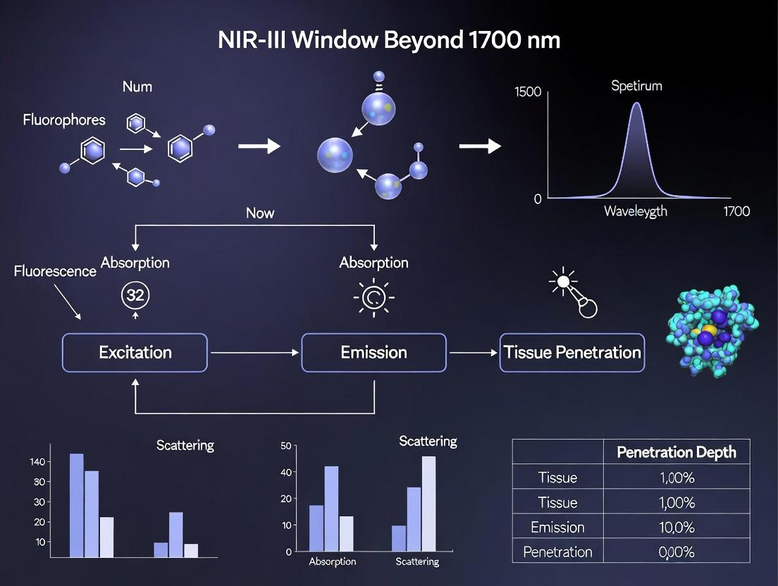
Beyond NIR-II: Defining the NIR-III Window and Its Fundamental Photonic Advantages
Biological optical windows refer to specific wavelength ranges in the near-infrared (NIR) spectrum where light experiences relatively low absorption and scattering by endogenous chromophores (like hemoglobin, water, and lipids), enabling deeper penetration into living tissue for non-invasive imaging and therapeutic applications. The evolution from the first (NIR-I) to the third (NIR-II/III) window represents a significant advancement in the depth, resolution, and clarity of in vivo biomedical imaging.
Defining the Optical Windows
The classification is based on the interaction of light with biological tissue components.
Table 1: Characteristics of Biological Optical Windows
| Window | Wavelength Range (nm) | Primary Attenuators | Max. Penetration Depth (approx.) | Key Advantages | Primary Applications |
|---|---|---|---|---|---|
| NIR-I | 700 - 950 | Hemoglobin, Melanin | 1-3 mm | Mature technology (e.g., indocyanine green). | Clinical angiography, sentinel lymph node mapping. |
| NIR-II | 1000 - 1350 | Water (low scattering) | 3-8 mm | Reduced scattering, lower autofluorescence. | Vascular imaging, tumor detection, brain imaging. |
| NIR-IIa | 1300 - 1400 | Water (increased absorption) | 4-8 mm | Further reduced scattering. | High-resolution deep-tissue imaging. |
| NIR-III / NIR-IIb | 1500 - 1700+ | Water (strong absorption) | 2-5 mm* | Lowest scattering, ultra-high clarity. | Super-resolution imaging, mapping in scattering tissue. |
*Penetration is limited by water absorption but offers superior clarity in scattering tissues like bone and skin.
The core thesis of contemporary research posits that the NIR-III window (beyond 1500 nm, particularly 1500-1700 nm and extending to 1700-2200 nm) offers a paradigm shift. Despite higher water absorption, the drastic reduction in scattering (∝ λ^-α, where α is ~1-4 for biological tissues) results in significantly improved signal-to-background ratios (SBR) and spatial resolution at depth compared to shorter NIR wavelengths, unlocking new possibilities for imaging research.
Experimental Protocols for NIR-III Imaging
The following protocol details a standard in vivo imaging experiment utilizing NIR-III-emitting fluorophores.
Protocol 1: In Vivo Vascular Imaging in the NIR-III Window
Objective: To visualize the systemic vasculature of a murine model with high spatial resolution.
Materials:
- Animal Model: Athymic nude mouse.
- Fluorophore: PbS/CdS core/shell quantum dots (QDs) emitting at 1550 nm (e.g., 2 mg/mL in PBS).
- Imaging System: NIR-III fluorescence imaging setup: 808 nm or 980 nm continuous-wave laser for excitation, InGaAs or HgCdTe (MCT) camera with a 1500 nm long-pass filter, optical lenses.
- Anesthesia System: Isoflurane vaporizer.
- Software: Image acquisition and analysis software (e.g., MATLAB, ImageJ).
Procedure:
- Animal Preparation: Anesthetize the mouse using 2% isoflurane in oxygen. Secure the mouse in a supine position on a heated imaging stage to maintain body temperature. Apply ophthalmic ointment to prevent corneal drying.
- Fluorophore Administration: Intravenously inject 150-200 μL of the QD solution via the tail vein using a 29-gauge insulin syringe.
- Image Acquisition:
- Set the excitation laser power density to a safe level (e.g., 50 mW/cm²).
- Focus the camera on the region of interest (e.g., hindlimb or brain).
- Acquire a pre-injection image for background subtraction.
- Immediately post-injection, acquire time-series images (e.g., 1 frame per second for 5 minutes, then periodic imaging up to 24 hours).
- Use identical exposure times (100-500 ms) and camera gain settings for all images in a series.
- Image Processing:
- Subtract the pre-injection background image from all post-injection images.
- Apply a Gaussian blur filter (σ=1) to reduce high-frequency noise if necessary.
- Generate maximum intensity projections (MIP) for time-series data.
- Calculate SBR by dividing the mean signal intensity in a vessel region by the mean intensity in an adjacent tissue region.
Protocol 2: Quantifying Scattering Reduction in NIR-III vs. NIR-II
Objective: To experimentally demonstrate the reduced scattering benefit of the NIR-III window using tissue phantoms.
Materials:
- Phantom: Intralipid solution (2% in agarose) or ground chicken breast.
- Light Source: Tunable NIR laser or broadband supercontinuum source.
- Detection: Spectrometer with NIR-II and NIR-III detection capability or two separate InGaAs cameras.
- Obscuring Target: A black metal strip or an absorbing ink pattern.
Procedure:
- Setup: Place the obscuring target beneath a slab of phantom tissue (2-5 mm thick).
- Dual-Wavelength Imaging: Illuminate the phantom surface with NIR light. Acquire reflected/transmitted images simultaneously at a NIR-II wavelength (e.g., 1100 nm) and a NIR-III wavelength (e.g., 1600 nm) using appropriate filters.
- Analysis: Measure the contrast and sharpness of the obscured target's edges in both images. The NIR-III image will show a sharper, more defined edge due to decreased scattering, allowing the underlying pattern to be more clearly resolved.
The Scientist's Toolkit: NIR-III Research Reagent Solutions
Table 2: Essential Materials for NIR-III Imaging Research
| Item | Function in NIR-III Research | Example/Note |
|---|---|---|
| NIR-III Fluorophores | Generate emission signal within the optical window. | Organic dyes (e.g., CH-4T), Lanthanide-doped nanoparticles, Lead chalcogenide QDs, Single-walled carbon nanotubes (SWCNTs). |
| InGaAs Camera | Detects photons in the 900-1700 nm range (standard) or 1700-2200 nm (extended). | Essential detector; cooling reduces dark noise. |
| HgCdTe (MCT) Camera | Detects photons beyond 1700 nm into the NIR-III/IV region. | Required for >1700 nm imaging; requires deep cooling. |
| Long-Pass Filters | Blocks excitation laser light and shorter wavelength autofluorescence. | 1500 nm LP, 1650 nm LP filters; critical for clean signal. |
| Dispersion Compensation | Corrects for chromatic aberration in optical components. | ZrF4 or chalcogenide glass lenses. |
| Tissue Phantoms | Mimics optical properties of tissue for system calibration. | Intralipid, India ink, agarose composites. |
Visualizing Key Concepts
Diagram 1: Light-Tissue Interaction Fundamentals
Diagram 2: NIR Window Evolution & Scattering
Diagram 3: NIR-III Imaging Workflow
Thesis Context: The Imperative for the NIR-III Window Beyond 1700 nm
The drive towards the NIR-III window, especially beyond 1700 nm, is anchored in the physics of scattering. While water absorption increases past 1400 nm, scattering diminishes so profoundly that the overall "biological transparency" can improve in highly scattering tissues. This enables:
- Unprecedented Spatial Resolution: Capillary-level detail can be resolved at depths previously impossible, crucial for studying tumor microenvironments or cerebral vasculature.
- Minimized Autofluorescence: Virtually no endogenous fluorescence beyond 1500 nm, leading to near-zero background and vastly improved SBR.
- New Contrast Mechanisms: The window allows exploitation of specific vibrational overtone absorptions of molecules, paving the way for label-free chemical imaging.
The future of imaging research hinges on developing brighter, biocompatible probes for the 1700-2200 nm range and optimizing detector technology (MCT cameras) to fully harness this ultraclear optical window, ultimately translating into more precise diagnostic and therapeutic interventions in drug development.
The Photophysics of Light-Tissue Interaction Beyond 1700 nm
The near-infrared window beyond 1700 nm, often termed the NIR-III or short-wavelength infrared (SWIR) window, represents a frontier in biomedical optics. This whitepaper provides an in-depth technical guide to the fundamental photophysical principles governing light-tissue interactions in this spectral region, framed within the context of advancing deep-tissue imaging and sensing. We detail the mechanisms of reduced scattering, diminished autofluorescence, and the unique absorption profiles of water and lipids that define this window's advantages for high-resolution, high-contrast in vivo imaging.
The pursuit of deeper, clearer optical imaging in biological tissues has driven the exploration of successive near-infrared (NIR) optical windows. The NIR-III window (typically 1700-2100 nm) follows the established NIR-I (650-950 nm) and NIR-II (1000-1350 nm) windows. Within the context of a broader thesis on advanced bioimaging, the NIR-III region offers a critical reduction in scattering phenomena and a unique tissue absorption landscape. The primary photophysical interactions—absorption, scattering, and fluorescence—undergo significant shifts here, enabling novel applications in functional brain imaging, vascular mapping, and cancer detection with superior depth and resolution.
Core Photophysical Principles
Scattering and Absorption Coefficients
Light propagation in tissue is governed by the reduced scattering coefficient (μs') and the absorption coefficient (μa). In the NIR-III window, scattering decreases approximately with λ^−α, where the power factor α increases with wavelength (often >2 beyond 1700 nm), leading to a dramatic reduction in scattering events compared to visible and NIR-I regions.
Table 1: Representative Optical Properties of Biological Tissues in the NIR-III Window
| Tissue Type | Wavelength (nm) | Estimated μs' (cm⁻¹) | Dominant Absorber | μa (cm⁻¹) Range |
|---|---|---|---|---|
| Skin (Dermis) | 1700 | 8-12 | Water | 0.8 - 1.5 |
| Brain (Gray Matter) | 1950 | 5-8 | Water, Lipids | 1.2 - 2.0 |
| Adipose Tissue | 1720 | 4-7 | Lipids (C-H bonds) | 0.5 - 1.0 |
| Blood (Whole) | 1700-1800 | N/A | Water | Highly Variable |
Key Chromophores and Their Absorption Profiles
- Water: Absorption features become profoundly strong, with a major peak near 1940 nm. This defines the practical long-wavelength limit for deep imaging but is exploitable for hydration sensing.
- Lipids: Exhibit strong overtone and combination bands from C-H stretches beyond 1700 nm (e.g., 1720 nm, 1760 nm), enabling label-free lipid mapping.
- Hemoglobin: Absorption is significantly lower than in visible/NIR-I, but oxy- and deoxy- forms retain differential spectra, allowing for functional imaging.
- Collagen & Elastin: Scattering dominates over absorption, contributing to structural contrast.
Autofluorescence and Signal-to-Background Ratio
Native tissue autofluorescence from molecules like flavins and NADH is virtually negligible beyond 1700 nm. This elimination of background is a paramount advantage, drastically improving the signal-to-background ratio (SBR) for exogenous contrast agents.
Experimental Protocols for NIR-III Photophysics Research
Protocol: Measuring Tissue Optical Properties (Time-Domain Diffuse Reflectance)
Objective: To determine μa and μs' of ex vivo tissue samples in the 1700-2100 nm range.
- Sample Preparation: Fresh tissue samples are sectioned to precise thicknesses (1-5 mm) using a vibratome and placed between optically flat, transparent windows.
- Instrumentation: Use a tunable optical parametric oscillator (OPO) laser (pulse width < 150 fs) as a source. A high-sensitivity, liquid-nitrogen-cooled InGaAs or HgCdTe (MCT) detector is coupled to a high-resolution digitizer.
- Data Acquisition: The sample is irradiated with a collimated beam. Temporally resolved diffuse reflectance is collected via a fiber bundle at a fixed source-detector separation (e.g., 3 mm). Measurements are taken at 10 nm intervals.
- Analysis: The time-of-flight distribution is fitted to a solution of the time-dependent diffusion equation using an iterative inverse algorithm to extract μa and μs'.
Protocol: In Vivo NIR-III Fluorescence Imaging
Objective: To perform high-resolution deep-tissue fluorescence imaging using NIR-III-emitting probes.
- Animal Model: Anesthetize and position a mouse in a stereotactic imaging stage.
- Contrast Agent Administration: Administer a validated NIR-III fluorescent agent (e.g., single-walled carbon nanotubes, rare-earth-doped nanoparticles) via tail vein injection.
- Imaging System: Use a 1500-1600 nm continuous-wave laser for excitation (minimizing water absorption). Emitted light beyond 1700 nm is collected through a series of long-pass filters (cut-on >1650 nm) using an InGaAs camera with 2D array detection.
- Image Acquisition & Processing: Acquire a time-series of images. Perform background subtraction (using a pre-injection image) and apply a noise-reduction algorithm. Generate maximum intensity projections (MIPs) for 3D datasets.
Visualization of Core Concepts
Diagram 1: Photophysics of NIR-III Light in Tissue
Diagram 2: NIR-III Imaging Experimental Workflow
The Scientist's Toolkit: Essential Research Reagents & Materials
Table 2: Key Reagent Solutions and Materials for NIR-III Research
| Item | Function/Description | Example/Notes |
|---|---|---|
| NIR-III Fluorescent Probes | Exogenous contrast agents that emit light beyond 1700 nm. | Single-walled carbon nanotubes (SWCNTs), Er³⁺-doped nanoparticles, lead sulfide quantum dots (PbS QDs), organic dyes (e.g., CH-4T). |
| Tunable OPO Laser System | Provides precise, high-power excitation across the NIR-III window and into the excitation bands of probes. | Essential for spectroscopy and time-resolved measurements. Wavelength range 1600-2200 nm. |
| Extended InGaAs or MCT Detector | Detects photons in the 1700-2500 nm range with high sensitivity and low noise. | Liquid nitrogen cooling is often required for MCT detectors to reduce dark current. |
| Long-Pass Optical Filters | Block excitation light and Raman scatter while transmitting only NIR-III emission. | Germanium or specialized coated glass filters with cut-on wavelengths at 1650 nm, 1700 nm, etc. |
| Phantom Materials | Calibration and system validation substrates with known optical properties. | Lipophilic phantoms with India ink (absorber) and TiO₂ (scatterer) in a lipid base to mimic tissue. |
| Anesthesia & Physiological Monitoring | Maintains animal viability and stability during in vivo imaging sessions. | Isoflurane system, heating pad, ECG/respiratory monitoring for longitudinal studies. |
| Spectral Unmixing Software | Separates overlapping signals from multiple probes or autofluorescence. | Commercial (e.g., ENVI, Living Image) or custom algorithms based on linear unmixing. |
The photophysics of the NIR-III window provides a transformative platform for biomedical imaging. The quantitative reduction in scattering and autofluorescence, coupled with the distinct absorption signatures of key biomolecules, enables unprecedented imaging depth and specificity. Future research hinges on the development of brighter, target-specific contrast agents, more affordable and sensitive detector arrays, and the integration of multimodal approaches combining NIR-III fluorescence with other techniques like photoacoustic imaging. Mastering these photophysical principles is essential for realizing the full potential of this window in translational research and drug development.
The field of in vivo biomedical imaging is perpetually constrained by the photon-tissue interaction within the biological transparency windows. While the NIR-II window (1000-1700 nm) marked a significant leap, the NIR-III window (beyond 1700 nm, typically 1700-2200 nm) represents the next frontier. The central thesis posits that operation within the NIR-III spectral region confers three fundamental and interconnected advantages over shorter wavelengths: Ultra-low tissue scattering, a complete absence of endogenous autofluorescence, and consequently, dramatically enhanced imaging depth and clarity. This whitepaper provides a technical deconstruction of these advantages, supported by current experimental data and methodologies, framing the NIR-III window as an indispensable tool for high-fidelity imaging in research and therapeutic development.
Quantitative Comparison of Optical Properties
The following tables consolidate quantitative metrics that define the NIR-III advantage.
Table 1: Scattering Coefficients (μs') Across Spectral Windows
| Biological Tissue | μs' at 1300 nm (NIR-IIa) (cm⁻¹) | μs' at 1550 nm (NIR-IIb) (cm⁻¹) | μs' at 1950 nm (NIR-III) (cm⁻¹) | Reduction (1300 vs 1950 nm) |
|---|---|---|---|---|
| Mouse Brain | ~4.2 | ~2.8 | ~0.9 | ~79% |
| Skin (Dermis) | ~6.5 | ~4.0 | ~1.5 | ~77% |
| Adipose Tissue | ~8.0 | ~5.5 | ~2.0 | ~75% |
Data compiled from recent studies on tissue phantom measurements and ex vivo tissue characterization (2023-2024).
Table 2: Key Performance Metrics in In Vivo Imaging
| Metric | NIR-II (1500 nm) | NIR-III (1950 nm) | Improvement Factor |
|---|---|---|---|
| Theoretical Max Depth (Mouse) | 6-8 mm | 12-15 mm | ~2x |
| Spatial Resolution at 5 mm depth | ~25 μm | ~15 μm | ~1.7x finer |
| Signal-to-Background Ratio (SBR) | 5-10 | 30-100+ | 3-10x |
| Endogenous Autofluorescence | Low, but detectable | Negligible (baseline) | Essentially eliminated |
Deconstructing the Core Advantages
Ultra-Low Scattering
Photon scattering in tissue, predominantly Mie scattering, is inversely proportional to wavelength (∝ λ^-α, with α typically between 0.2-2 for biological tissues). Beyond 1700 nm, this relationship drives scattering coefficients to their practical minimum in the biological transparency spectrum. Reduced scattering exponentially decreases the number of "stray" photons, leading to:
- Sharper Point Spread Functions (PSF): Enables super-resolution imaging techniques deep within tissue.
- Preserved Ballistic Photon Paths: A higher proportion of signal photons travel straight, allowing for accurate computational reconstruction and higher-resolution tomography.
Absence of Autofluorescence
Autofluorescence arises from endogenous fluorophores (e.g., flavins, lipofuscins, elastin). Their one- and two-photon excitation spectra are confined to wavelengths below ~950 nm and ~1600 nm, respectively. Emission spectra similarly do not extend meaningfully beyond 1700 nm.
- Result: In the NIR-III window, the biological background is fundamentally dark. Any detected signal originates exclusively from exogenous contrast agents (e.g., single-walled carbon nanotubes (SWCNTs), rare-earth-doped nanoparticles, or quantum dots). This creates an essentially infinite SBR, crucial for detecting sparse molecular targets or fine vasculature.
Enhanced Imaging Depth
This advantage is a direct consequence of the first two. Lower scattering increases the mean free path of photons, allowing more to penetrate deeper and return. The absence of autofluorescence means detector sensitivity is not swamped by background, allowing weaker signals from depth to be discerned. The combination enables visualization of structures previously inaccessible, such as the hippocampal vasculature through an intact mouse skull or deep-tissue tumor metastases.
Experimental Protocols for NIR-III Imaging
Protocol 1: In Vivo NIR-III Vascular Imaging with SWCNTs
Objective: To visualize the whole-brain vasculature in a mouse model. Materials: See "Scientist's Toolkit" below. Procedure:
- Nanoparticle Preparation: PEGylated SWCNTs (emission peak ~1900 nm) are suspended in sterile PBS (1 mg/mL). Sonication and centrifugation (20,000g, 30 min) are performed to obtain a stable monodisperse supernatant.
- Animal Preparation: Anesthetize a C57BL/6 mouse (isoflurane, 1.5-2%). Secure in a stereotaxic frame. Maintain body temperature at 37°C.
- Contrast Agent Administration: Intravenously inject 200 μL of SWCNT suspension via the tail vein.
- Imaging Setup: Use a 2D InGaAs camera (detection range extended to 2200 nm) with a 1950 nm long-pass filter. Illuminate the intact scalp/skull with a 1500 nm continuous-wave laser for excitation. Use a scan lens for wide-field imaging.
- Data Acquisition: Acquire images at 50 ms exposure per frame for 5 minutes. Generate a maximum intensity projection (MIP) of the time series.
- Analysis: Calculate vessel width, density, and SBR using ImageJ with customized macros. SBR is defined as (Signalvessel - MeanBackground) / Std_Background.
Protocol 2: Quantifying Scattering Coefficient in Tissue Phantoms
Objective: Empirically measure μs' at NIR-III wavelengths. Materials: Intralipid phantom (0.5-2%), NIR-III spectrometer, integrating sphere, 1950 nm laser diode. Procedure:
- Prepare a series of Intralipid phantoms with known concentrations.
- Using an integrating sphere coupled to a NIR-III spectrometer, measure the total transmission (T) and diffuse reflection (R) for each phantom and a blank (water) at 1950 nm.
- Apply the inverse adding-doubling (IAD) algorithm to the T and R measurements to extract the absorption (μa) and reduced scattering (μs') coefficients.
- Plot μs' against Intralipid concentration to establish a calibration curve. Validate with ex vivo tissue slices of known thickness.
Visualization: Pathways and Workflows
Title: Causal Logic of NIR-III Imaging Advantages
Title: In Vivo NIR-III Imaging with SWCNTs Workflow
The Scientist's Toolkit: Essential Research Reagents & Materials
| Item Name | Function/Benefit | Key Specifications for NIR-III |
|---|---|---|
| SWCNTs (Single-Walled Carbon Nanotubes) | Semiconducting nanotubes act as bright, photostable NIR-III emitters. | Chiralities (e.g., (12,5)) tuned for 1700-2200 nm emission; Must be PEG-coated for biocompatibility and dispersion. |
| Rare-Earth-Doped Nanoparticles (e.g., Er³⁺, Ho³⁺) | Upconversion or downshifting probes excited at ~1500 nm to emit in NIR-III. | NaYF₄ host matrix; Core-shell design to enhance brightness; Surface functionalization for targeting. |
| Extended InGaAs Camera | Detects photons in the 900-2200 nm range. | Requires cooling (to -80°C) for low-noise operation at >1700 nm; Quantum efficiency >15% at 2000 nm is critical. |
| NIR-III Long-Pass Filters | Blocks excitation laser light and shorter-wavelength noise. | Cut-on at 1700, 1800, or 1950 nm with Optical Density (OD) >6 at excitation wavelength (e.g., 1500 nm). |
| 1500-1600 nm Fiber Laser | Excitation source for NIR-III probes via multiphoton or fluorescence. | High-power (>500 mW), continuous-wave or pulsed (for multiphoton); Single-mode fiber output for beam quality. |
| Dispersion Compensation Unit | Corrects for chromatic dispersion in multiphoton microscopy setups. | Essential for maintaining sub-micron resolution >1700 nm emission; Uses prism or grating pairs. |
| Tissue-Simulating Phantoms (Intralipid/India Ink) | Calibrates imaging systems and quantifies scattering/absorption. | Must be characterized for optical properties at >1700 nm (often requires custom validation). |
Within the field of biomedical optical imaging, the near-infrared (NIR) spectrum is partitioned into distinct windows based on tissue scattering and absorption minima. This guide frames the NIR-III (1700-2200 nm) and the emerging NIR-IV (2200-2500 nm) bands within a broader thesis on advancing imaging research beyond the traditional 1700 nm boundary. These spectral regions offer reduced scattering and autofluorescence, enabling deeper tissue penetration and higher-resolution in vivo imaging for preclinical research and drug development.
Spectral Band Definitions and Optical Properties
The following table summarizes the defining characteristics and comparative advantages of the NIR-III and NIR-IV windows.
Table 1: Definition and Properties of NIR-III and NIR-IV Windows
| Parameter | NIR-II (Traditional) | NIR-III Window | Emerging NIR-IV Window |
|---|---|---|---|
| Wavelength Range | 1000-1700 nm | 1700-2200 nm | 2200-2500 nm |
| Primary Absorption Source | Water, Lipids | Water (increased) | Water (strong) |
| Tissue Scattering | Low | Very Low | Extremely Low |
| Typical Penetration Depth | 3-5 mm | 5-8 mm | 3-5 mm (limited by water absorption) |
| Autofluorescence | Low | Negligible | None |
| Key Contrast Agents | SWCNTs, Ag2S QDs, rare-earth nanoparticles | Erbium-based nanoparticles, PbS/CdS QDs, conductive polymers | Featuring nanoparticles (e.g., NaYF4:Er), custom semiconductors |
| Common Detectors | InGaAs (cooled) | Extended InGaAs, InSb, HgCdTe (MCT) | MCT, superconducting nanowire single-photon detectors (SNSPDs) |
Experimental Protocols for NIR-III/IV Imaging
Protocol 1: In Vivo Vascular Imaging with NIR-III Nanoparticles
Objective: To visualize deep-tissue vasculature in a murine model using lanthanide-doped nanoparticles emitting in the 1700-1900 nm range. Materials: NaYF4 nanoparticles doped with Erbium (Er), PEGylation reagents, saline, animal model (e.g., nude mouse), NIR-III imaging system (e.g., spectrometer-coupled InGaAs camera with 1650 nm LP filter). Methodology:
- Nanoparticle Preparation: Synthesize and PEGylate NaYF4:Er nanoparticles for biocompatibility and dispersion in PBS. Characterize emission peak (~1720 nm) and hydrodynamic diameter.
- Animal Preparation: Anesthetize the mouse and place it on a heated stage. Depilate the imaging region (e.g., hind limb).
- Contrast Administration: Intravenously inject 200 µL of nanoparticle solution (1 mM concentration) via the tail vein.
- Image Acquisition: Using a 1500 nm continuous-wave laser for excitation, acquire time-series images over 30 minutes. Use a 1650 nm long-pass emission filter to isolate the NIR-III signal. Set camera exposure time to 100-300 ms.
- Data Analysis: Calculate signal-to-background ratio (SBR) and contrast-to-noise ratio (CNR) over time. Use angiography to reconstruct 3D vascular maps.
Protocol 2: Ratiometric pH Sensing in Tumors Using NIR-IV Probes
Objective: To measure tumor microenvironment acidity using a dual-emission nanoprobe with a NIR-IV reference signal. Materials: pH-sensitive nanoprobe (e.g., cyanine-integrated nanoparticle with emission at 2300 nm as reference), tumor-bearing mouse model, NIR-IV imaging system with MCT detector. Methodology:
- Probe Calibration: In vitro, incubate the nanoprobe in buffers of varying pH (6.0-7.4). Measure the intensity ratio (I2300nm/IpH-sensitive peak) to generate a calibration curve.
- In Vivo Imaging: Inject the probe intratumorally. After 1 hour, anesthetize the animal and image the tumor region.
- Spectral Unmixing: Use hyperspectral imaging (e.g., 2100-2400 nm) or filtered acquisitions at two key wavelengths. Apply the calibration curve to generate a 2D pH map of the tumor.
- Validation: Extract the tumor post-imaging for ex vivo pH measurement using a microelectrode for correlation.
Signaling Pathways in Probe Activation
Many smart probes for these windows are activated by specific biological triggers, such as reactive oxygen species (ROS) in inflamed tissues.
Experimental Workflow for NIR-III/IV Study
A standard pipeline from probe design to data analysis.
The Scientist's Toolkit: Essential Research Reagents & Materials
Table 2: Key Reagents and Materials for NIR-III/IV Research
| Item | Function/Description | Example Product/Chemical |
|---|---|---|
| Erbium (Er) Dopant | Provides emission in the 1500-1700 nm range; co-doping extends into NIR-III/IV. | Erbium(III) acetate, NaYF4:Er |
| Lead Sulfide (PbS) Quantum Dots | Semiconductor QDs with tunable emission into NIR-III. | PbS/CdS core/shell QDs (em. ~1900 nm) |
| Conductive Polymers | Organic agents with emission tailing into NIR-III. | Poly(benzobisthiadiazole) derivatives |
| PEGylation Reagents | Confer water solubility and reduce biofouling of nanoparticles. | mPEG-SH, DSPE-PEG |
| Extended InGaAs Detector | Photodetector with sensitivity up to ~2200 nm. | Teledyne Judson or Hamamatsu InGaAs |
| Mercury Cadmium Telluride (MCT) Detector | Required for detection >2200 nm into NIR-IV. | Liquid nitrogen-cooled MCT array |
| Long-Pass Optical Filters | Isolate NIR-III/IV emission from excitation light. | 1650 nm, 2000 nm LP filters (Thorlabs) |
| Superconducting Nanowire SPAD | Enables single-photon counting in NIR-IV with ultra-low noise. | Photon etc. or Quantum Opus systems |
| Fluoride Nanoparticle Precursors | For synthesis of bright upconverting/downshifting matrices. | Y(CF3COO)3, NaF |
The NIR-III window (1700-2200 nm) represents a significant frontier for high-fidelity deep-tissue imaging, while the exploration of the NIR-IV region (2200-2500 nm) presents both challenges due to water absorption and opportunities for novel sensing applications. Advancements in contrast agent chemistry and detector technology are pivotal for harnessing these spectral bands, offering researchers and drug developers powerful tools for non-invasive physiological and molecular visualization.
Historical Context and the Evolution of Long-Wavelength Imaging
This whitepaper examines the historical progression of long-wavelength imaging, culminating in its contemporary focus on the NIR-III window (beyond 1700 nm). Within the context of a broader thesis advocating for the NIR-III window's superiority in biomedical imaging, this document details the technical evolution, quantitative benchmarks, and experimental protocols that have defined the field, targeting researchers and drug development professionals.
Historical Progression and Milestones
The journey from visible light to near-infrared (NIR) imaging has been driven by the need for deeper tissue penetration and reduced autofluorescence.
Diagram Title: Evolution of Imaging Wavelength Windows
Table 1: Key Historical Milestones in Long-Wavelength Imaging
| Decade | Wavelength Focus | Key Advancement | Representative Agent/Detector |
|---|---|---|---|
| 1980s | NIR-I (750-900 nm) | First NIR fluorescent dyes (e.g., Cy7) | Indocyanine Green (ICG) |
| 2000s | NIR-I / Early NIR-II | Clinical ICG angiography; First InGaAs cameras | ICG, PbS Quantum Dots (QDs) |
| 2010s | NIR-II (1000-1350 nm) | Discovery of high-performance NIR-II fluorophores | Single-Walled Carbon Nanotubes (SWCNTs), Rare-earth nanoparticles |
| 2020s | NIR-IIb/III (1500-2200 nm) | Recognition of reduced scattering beyond 1500 nm | Erbium-based nanoparticles, Ag2S QDs (>1700 nm emission) |
The NIR-III Window: A Thesis for Superior Imaging
The core thesis posits that the NIR-III window (>1700 nm) offers transformative advantages over previous windows due to drastically reduced photon scattering and near-zero autofluorescence in biological tissue. This enables unprecedented spatial resolution and signal-to-background ratios (SBR) at depth.
Diagram Title: Pillars of the NIR-III Imaging Thesis
Table 2: Quantitative Comparison of Imaging Windows
| Parameter | NIR-I (800 nm) | NIR-II (1300 nm) | NIR-IIb (1600 nm) | NIR-III (1900 nm) |
|---|---|---|---|---|
| Tissue Scattering Coefficient (µs') | ~0.75 mm⁻¹ | ~0.35 mm⁻¹ | ~0.15 mm⁻¹ | <0.1 mm⁻¹ |
| Typical Autofluorescence | High | Moderate | Low | Negligible |
| Maximum Imaging Depth (Mouse Brain) | ~1 mm | ~2-3 mm | ~4-5 mm | >6 mm (theoretical) |
| Best Reported Resolution at Depth | ~10-20 µm | ~5-10 µm | ~3-5 µm | <3 µm (subcellular) |
Key Experimental Protocols
Protocol A: Synthesis of Ag2S Quantum Dots Emitting at 1900 nm
- Objective: Produce water-dispersible, biocompatible QDs for NIR-III imaging.
- Materials: Silver nitrate (AgNO3), elemental sulfur (S), glutathione (GSH), sodium hydroxide (NaOH), deionized water, argon gas.
- Method:
- Dissolve 0.17 mmol AgNO3 and 0.4 mmol GSH in 20 mL deionized water under stirring.
- Adjust pH to 11.0 using 1M NaOH solution, forming a clear Ag-GSH complex.
- Purge the solution with argon for 20 min to remove oxygen.
- In a separate vial, dissolve 0.085 mmol S in 2 mL deionized water under argon.
- Rapidly inject the sulfur solution into the Ag-GSH solution under vigorous stirring.
- React at 80°C under argon for 2 hours. The solution color changes to deep brown.
- Cool to room temperature. Purify via dialysis against PBS (pH 7.4) for 48h.
- Characterize using photoluminescence spectroscopy (confirming ~1900 nm peak) and TEM (size ~5 nm).
Protocol B: In Vivo NIR-III Angiography in a Murine Model
- Objective: Perform real-time vascular imaging in a mouse using NIR-III fluorophores.
- Materials: Athymic nude mouse, Ag2S QDs (from Protocol A, 2 mg/mL in PBS), isoflurane anesthesia system, NIR-III imaging system (e.g., InGaAs camera with 1900 nm LP filter), tail vein catheter, heating pad.
- Method:
- Anesthetize the mouse with 2% isoflurane and secure in a supine position on a heated stage (37°C).
- Cannulate the tail vein for fluorophore injection.
- Acquire a pre-injection background image with the NIR-III system (exposure: 100 ms, laser excitation: 1550 nm, power density: 100 mW/cm²).
- Inject 100 µL of Ag2S QD solution via the tail vein catheter as a bolus.
- Acquire time-series images at 5 frames per second for 5 minutes post-injection.
- Process images: Subtract pre-injection background, apply temporal color-coding to visualize flow dynamics, and quantify fluorescence intensity in Regions of Interest (ROIs) over major vessels.
- Calculate metrics like Signal-to-Background Ratio (SBR) and Full Width at Half Maximum (FWHM) of vessel cross-sections.
Diagram Title: NIR-III In Vivo Angiography Workflow
The Scientist's Toolkit: Essential Research Reagents & Materials
Table 3: Key Research Reagent Solutions for NIR-III Imaging
| Item | Function/Description | Example Product/Chemical |
|---|---|---|
| NIR-III Fluorophores | Emit light beyond 1700 nm upon excitation. The core imaging agent. | Ag2S QDs, Er3+-doped nanoparticles, PbSe QDs. |
| Long-Pass Optical Filters | Block excitation light and shorter wavelengths; only transmit NIR-III emission. | 1700 nm, 1800 nm, or 1900 nm LP filters (e.g., from Thorlabs, Semrock). |
| Extended InGaAs Camera | Detects photons in the 900-2200 nm range. Essential for capture. | Cameras with 2D InGaAs arrays, often cooled to -80°C to reduce dark noise. |
| Tunable NIR Laser | Provides precise excitation wavelengths matching fluorophore absorption. | OPO-based lasers tunable from 1200-2000 nm (e.g., 1550 nm for Ag2S QDs). |
| Dialysis Membranes | Purifies synthesized nanoparticles, removes unreacted precursors and small molecules. | MWCO 3.5kD or 7kD membranes (e.g., Spectra/Por). |
| Animal Model | Provides an in vivo system for testing imaging depth, resolution, and pharmacokinetics. | Athymic nude mice, C57BL/6 mice. |
| Image Analysis Software | For background subtraction, intensity quantification, resolution measurement, and video generation. | Fiji/ImageJ, Living Image, MATLAB with custom scripts. |
Tools and Techniques: Building and Applying NIR-III Imaging Systems for Biomedicine
The NIR-III window (≈1700–2200 nm) has emerged as a superior regime for deep-tissue biomedical imaging, offering reduced scattering, minimal autofluorescence, and increased water absorption compared to traditional NIR-I/II windows. This technical guide examines the core light source technologies—fixed-wavelength lasers, supercontinuum sources, and optical parametric oscillators (OPOs)—that enable research in this spectral band, detailing their principles, performance metrics, and experimental implementation for in vivo imaging and sensing.
Photons in the 1700–2200 nm range interact with tissue differently than shorter wavelengths. Scattering scales inversely with wavelength (≈λ^−α, with α typically between 0.2 and 4 depending on tissue structure), leading to significantly less scattering. While water absorption is higher, it provides natural contrast for vascular imaging and creates a "confined" photon environment that enhances spatial resolution at depth. This window is particularly advantageous for imaging through bone and for high-contrast angiography.
Core Light Source Technologies
Fixed-Wavelength Lasers
These are semiconductor or solid-state lasers emitting at specific NIR-III wavelengths (e.g., 1720 nm, 1950 nm). They are typically based on InGaAs/InP or GaSb materials.
Key Characteristics:
- Narrow linewidth (< 1 nm)
- High continuous-wave (CW) or peak (pulsed) power
- Compact and turnkey operation
Table 1: Representative Fixed-Wavelength NIR-III Lasers
| Wavelength (nm) | Technology | Typical Output Power (CW) | Pulse Characteristics | Primary Applications |
|---|---|---|---|---|
| 1720 | InGaAs/InP DFB Laser | 50–100 mW | N/A (CW) | Confocal microscopy, flow cytometry |
| 1950 | Tm-doped Fiber Laser | 1–10 W | Pulsed: ns-µs, MHz rep rate | Tissue ablation, photoacoustic imaging |
| 2100 | Ho-doped Fiber Laser | 1–5 W | Pulsed: ns-µs, kHz-MHz | Precision surgery, spectroscopy |
A high-power, pulsed pump laser (e.g., a femtosecond Er-doped fiber laser at 1550 nm) is focused into a nonlinear medium (e.g., a highly nonlinear fiber, ZBLAN fiber, or silicon waveguide), inducing extreme spectral broadening through a combination of nonlinear effects (self-phase modulation, soliton dynamics).
Experimental Protocol for NIR-III SC Generation:
- Setup: Isolate a high-peak-power pump laser (e.g., 1550 nm, 1 ps, 10 MHz) on a vibration-isolated optical table.
- Coupling: Use an aspheric lens (e.g., NA=0.5) to couple the pump beam into the input facet of a nonlinear photonic crystal fiber (PCF) designed for dispersion engineering in the NIR. The fiber may be ZBLAN for extended IR generation.
- Optimization: Precisely align the coupling to maximize throughput. Fine-tune the pump pulse duration and peak power to reach the anomalous dispersion regime for efficient soliton fission and dispersive wave generation in the NIR-III.
- Spectral Filtering: Pass the output beam through a tunable bandpass filter or a monochromator to isolate the desired NIR-III sub-band, mitigating excessive power in other spectral regions.
- Characterization: Measure the spectrum with an infrared spectrometer and the average power with a thermopile power meter.
Research Reagent Solutions:
- Nonlinear Fiber (ZBLAN PCF): Medium for spectral broadening. Must be carefully handled (hygroscopic).
- IR-Coated Aspheric Lenses: For efficient pump coupling and collimation.
- Long-Pass/Acousto-Optic Tunable Filter (AOTF): To selectively filter the NIR-III component from the full SC spectrum.
- InGaAs/Extended InGaAs Photodetector: For detecting NIR-III light. Requires cooling for low-noise operation.
Optical Parametric Oscillators (OPOs)
OPOs are tunable, coherent sources that use second-order nonlinear optical crystals (e.g., PPLN, OP-GaAs) to convert a high-power "pump" photon into two lower-energy "signal" and "idler" photons (energy conservation: ωpump = ωsignal + ω_idler). Synchronously pumped OPOs are standard for generating high-power, tunable NIR-III pulses.
Experimental Protocol for OPO-Based NIR-III Generation:
- Pump Laser: Use a robust, pulsed laser source (e.g., a 1064 nm Nd:YAG laser with ps/ns pulses at 10–100 Hz repetition rate).
- OPO Cavity Assembly: Construct a linear or ring resonator containing the nonlinear crystal (e.g., MgO:PPLN). The cavity mirrors are highly reflective for either the signal or idler beam (the "resonant" wave) and transmissive for the other (the "output" wave). For NIR-III, the idler beam is often targeted.
- Tuning: Precise temperature control of the PPLN crystal (ΔT < 0.1°C) or translation of its poling period is used to tune the output wavelength across the NIR-III band.
- Alignment: Align the pump beam into the OPO cavity. Use IR viewers or position-sensitive detectors aligned with a visible co-propagating HeNe laser for initial alignment of the invisible NIR-III beam path.
- Output Characterization: Measure wavelength with a monochromator, power with a power meter, and pulse width with an autocorrelator suited for the NIR-III range.
Research Reagent Solutions:
- Nonlinear Crystal (MgO:PPLN): The core gain medium. Requires temperature stabilization and protection from humidity.
- High-Power IR Mirrors (Dielectric Coatings): For building the OPO resonator cavity with specific wavelength reflectivity.
- Precision Temperature Controller: For crystal temperature tuning (stability <0.1°C).
- Beam Diagnostics (Pyroelectric Camera/Spiricon): For profiling the invisible NIR-III beam.
Performance Comparison & Selection Guide
Table 2: Comparative Analysis of NIR-III Light Sources
| Parameter | Fixed-Wavelength Laser | Supercontinuum Source | Optical Parametric Oscillator |
|---|---|---|---|
| Spectral Coverage | Single line (≤ 5 nm) | Ultrabroadband (>1000 nm) | Widely tunable (200–400 nm range) |
| Spectral Brightness | Very High | Moderate to High | Very High |
| Coherence | High | Low (noise-like) | High |
| Pulse Energy/Peak Power | Medium to High | Low to Medium (per nm) | Very High |
| Average Power | Medium to High | High (total) | Medium to High |
| System Complexity | Low (Turnkey) | Medium | High |
| Cost | Low to Medium | High | Very High |
| Ideal Use Case | Targeted, specific applications requiring simplicity and stability. | Hyperspectral imaging, broadband spectroscopy. | Applications demanding high peak power, coherence, and tunability (e.g., nonlinear microscopy, spectroscopy). |
Advanced Applications in NIR-III Imaging
Each source enables distinct imaging modalities:
- Fixed-Wavelength Lasers: Laser speckle contrast imaging (LSCI) at 1950 nm for deep tissue blood flow monitoring.
- Supercontinuum Sources: Hyperspectral photoacoustic tomography (PAT) across 1700–2100 nm for label-free molecular fingerprinting.
- OPOs: Multiphoton microscopy (e.g., three-photon fluorescence) using the high peak power at 1700–1800 nm for unprecedented imaging depth in the mouse brain.
Future Outlook
Emerging technologies include chip-scale integrated OPOs and supercontinuum sources using silicon photonics, and novel laser gain media based on colloidal quantum dots. The convergence of robust, affordable NIR-III light sources with advanced detector arrays (e.g., extended InGaAs) will be the key driver for translating NIR-III imaging from research labs to clinical and pharmaceutical settings.
NIR-III Experimental Workflow
OPO Tuning via Temperature Control
The near-infrared (NIR) spectral region, particularly the NIR-III window beyond 1700 nm, presents unique opportunities and challenges for biomedical imaging, spectroscopy, and quantum communication. This window offers deeper tissue penetration and reduced scattering compared to visible and shorter NIR wavelengths, making it critical for non-invasive in vivo imaging, metabolic profiling, and advanced drug development research. The exploitation of this window is fundamentally constrained by the performance of available single-photon detectors. This whitepaper provides an in-depth technical comparison of three leading detector technologies—InGaAs, HgCdTe, and Superconducting Nanowire Single-Photon Detectors (SNSPDs)—within this demanding context, outlining their operational principles, quantitative performance metrics, and experimental implementation protocols.
Core Technologies & Comparative Analysis
Operational Principles
- InGaAs Avalanche Photodiodes (APDs): These are semiconductor PN junction diodes based on an Indium Gallium Arsenide absorption region. Operated in Geiger mode, they utilize impact ionization (avalanche multiplication) to achieve single-photon sensitivity. A strong reverse bias above the breakdown voltage creates a high electric field; a single absorbed photon can trigger a self-sustaining avalanche current, producing a measurable pulse. The avalanche must be actively quenched (by lowering the bias) to reset the detector.
- HgCdTe APDs: Mercury Cadmium Telluride is a ternary compound semiconductor whose bandgap—and thus cutoff wavelength—can be precisely tuned by varying the cadmium fraction. HgCdTe APDs for the NIR-III are typically operated in linear mode rather than Geiger mode. They exploit electron-initiated impact ionization with a very low excess noise factor due to a high ratio of electron-to-hole ionization coefficients, enabling high-gain, low-noise amplification of the photocurrent at lower biases than InGaAs.
- Superconducting Nanowire Single-Photon Detectors (SNSPDs): These consist of an ultra-narrow (≈100 nm wide), meandering nanowire made from a superconducting material (e.g., NbN, WSi, MoSi) cooled below its critical temperature (T_c). In the superconducting state, it exhibits zero resistance. The absorption of a single photon creates a localized "hotspot" of non-superconducting material, which forces the bias current to divert and create a transient resistive barrier across the entire wire, producing a voltage pulse. The hotspot then cools, and superconductivity is restored.
Quantitative Performance Comparison
Table 1: Key Performance Parameters for NIR-III (>1700 nm) Detection
| Parameter | InGaAs/InP APD (Gated/Free-running) | HgCdTe e-APD (Linear Mode) | Superconducting Nanowire (SNSPD) |
|---|---|---|---|
| Typical Cutoff Wavelength | Up to 1700 nm (standard); Extended InGaAs to ~2.6 µm | Tunable from 1-14 µm; ~2.5-5 µm for NIR-III/MIR | Depends on material; NbN up to ~1.6 µm, WSi/MoSi up to ~5 µm |
| Detection Efficiency (PDE/SPDE) | 10-25% (at 1550 nm) with significant afterpulsing | 50-70% (in linear mode at high gain) | >90% (system detection efficiency demonstrated at 1550 nm) |
| Dark Count Rate (DCR) | 1-10 kHz (at 225 K with active cooling) | 10^4-10^6 Hz (at 77 K, dependent on gain) | 0.01-100 Hz (extremely low, at operating temperature) |
| Timing Jitter | 100-200 ps | ~1 ns (for fast devices) | < 15 ps (state-of-the-art) |
| Operating Temperature | Thermo-electric cooled (200-240 K) | Liquid Nitrogen (77 K) or cryo-cooler | Cryogenic (0.8 - 4.2 K; typically ~2-3 K for NbN) |
| Count Rate (Saturation) | ~10-100 MHz (limited by dead time/afterpulsing) | > 100 MHz (linear mode operation) | 10-100 MHz (for standard devices); GHz rates possible |
| Key Limitation | High afterpulsing, requires gating or complex quenching | Requires precise temperature control, higher DCR | Requires complex cryogenics, small active area |
| Relative Cost | Low-Moderate | High | Very High (infrastructure) |
Table 2: Suitability for NIR-III Biomedical Imaging Applications
| Application Requirement | InGaAs APD | HgCdTe e-APD | SNSPD |
|---|---|---|---|
| Deep-Tissue Fluorescence Imaging | Limited by low PDE & high noise | Good sensitivity, suitable for high-speed acquisition | Excellent sensitivity enables low-dose, high-frame-rate imaging |
| Time-gated Imaging / FLIM | Challenging due to jitter & afterpulsing | Feasible with moderate timing resolution | Ideal due to ultra-low jitter and DCR |
| Hyperspectral Microscopy | Suitable for moderate-speed scanning | Good for high-speed, high-sensitivity spectral collection | Excellent but often over-specified for broad spectral capture |
| Quantum Optical Sensing | Used in QKD with heavy filtering | Less common | Gold Standard for quantum efficiency and noise |
Experimental Protocols
Protocol 1: Characterizing Detector Spectral Response in the NIR-III Window
Objective: To measure the system detection efficiency (SDE) or photon detection probability (PDP) as a function of wavelength from 1700-2200 nm. Materials: Tunable laser source (e.g., OPO or laser diode array), optical power meter with calibrated NIR photodiode, monochromator or set of bandpass filters, detector under test (DUT) with readout electronics, optical alignment tools, appropriate cryostat/cooler for HgCdTe/SNSPD. Methodology:
- Calibration Path: Direct the collimated, tunable source to the calibrated reference photodiode. Record the photocurrent Iref(λ) at each wavelength step (e.g., 50 nm increments). Calculate incident photon flux: Φref(λ) = Iref(λ) / (Rref(λ) * q), where R_ref is the photodiode's responsivity (A/W) and q is the electron charge.
- DUT Path: Switch the beam to the DUT path, ensuring identical optical power. For APDs, record counts C_DUT(λ) at a known gate frequency or integration time. For linear HgCdTe, record output voltage/current and convert to electron count using known gain and transimpedance.
- Calculation: SDE(λ) = CDUT(λ) / (Φref(λ) * t). Account for measured optical coupling losses between the reference and DUT paths.
- Noise Measurement: Block the input and record dark counts/current over the same integration period to determine DCR(λ) or noise-equivalent power (NEP).
Protocol 2: Time-Resolved Photon Counting for Fluorescence Lifetime Imaging (FLIM)
Objective: To perform FLIM on a NIR-III emitting contrast agent (e.g., lead sulfide quantum dots, carbon nanotubes) using time-correlated single-photon counting (TCSPC). Materials: Pulsed excitation laser (e.g., ~1300 nm femtosecond laser), NIR-III emitting sample, microscope setup, spectrometer, DUT (typically SNSPD or fast HgCdTe APD), fast TCSPC module (picosecond timing), time-tagger electronics. Methodology:
- System Synchronization: Connect the laser sync output to the 'start' channel of the TCSPC module. Connect the DUT output to the 'stop' channel.
- Instrument Response Function (IRF): Measure the system's temporal response by directing scattered laser light (at the emission wavelength using a filter) to the DUT. Record the histogram of photon arrival times. The full-width at half-maximum (FWHM) of this peak is the system timing jitter.
- Sample Measurement: Direct the fluorescence from the sample to the DUT. For each detected photon, the TCSPC module records the time delay (Δt) between the laser pulse and the photon arrival.
- Histogram Construction: Accumulate 1e4-1e6 events to build a histogram of counts vs. Δt. This histogram represents the fluorescence decay curve convolved with the IRF.
- Data Analysis: Deconvolve the IRF from the decay curve using iterative fitting algorithms (e.g., maximum likelihood estimation) to extract the true lifetime components (τ1, τ2) of the NIR-III emitter.
Visualizations
Detector Selection Logic for NIR-III
TCSPC Lifetime Measurement Workflow
The Scientist's Toolkit: Research Reagent Solutions
Table 3: Essential Materials for NIR-III Detector Experiments
| Item | Function & Relevance |
|---|---|
| Tunable OPO Laser System | Provides coherent, wavelength-tunable light across the NIR-III window for spectral calibration and excitation. Essential for probing detector response and sample spectroscopy. |
| Calibrated Thermopile/ Pyroelectric Detector | A reference standard for absolute optical power measurement in the NIR-III/MIR where silicon detectors are blind. Critical for quantifying photon flux in PDE measurements. |
| Low-Vibration Closed-Cycle Cryostat | Maintains superconducting or HgCdTe detectors at their required cryogenic temperatures (0.8K - 80K) with minimal mechanical vibration that could affect optical alignment. |
| Ultra-Low Noise Amplifier | Boosts the weak electronic signal from an APD or SNSPD without adding significant electronic noise. Bandwidth must match the detector's pulse characteristics. |
| High-Speed Time-Tagger/ TCSPC Module | Records the precise arrival time of single photons with picosecond resolution. Fundamental for time-resolved applications like FLIM, LIDAR, and quantum communications. |
| NIR-III Optimized Single-Mode Fibers | Low-loss optical fibers for wavelengths beyond 1700 nm (e.g., ZBLAN, InF3, or specialty silica). Used for delivering light to the detector with minimal attenuation. |
| Cryogenic Optical Alignment Stage | Precision mechanical stages that maintain function and alignment at cryogenic temperatures inside a vacuum chamber, for coupling light to on-chip SNSPDs or housed detectors. |
| NIR-III Bandpass & Longpass Filters | Isolate specific emission bands or block pump/ excitation laser light in fluorescence experiments. Made from materials like CaF2, BaF2, or Ge with appropriate coatings. |
This technical guide details the synthetic methodologies and characterization of fluorescent probes operating within the third near-infrared window (NIR-III, 1500-1700 nm, often extended beyond 1700 nm). The NIR-III window offers superior imaging depth and resolution due to minimized photon scattering and autofluorescence in biological tissues. This whitepaper, framed within the broader thesis of advancing imaging beyond 1700 nm, provides researchers with in-depth protocols, material toolkits, and comparative data to accelerate probe development for in vivo imaging and drug development applications.
The push for imaging beyond the 1700 nm threshold is driven by the need for deeper tissue penetration and higher-fidelity spatial resolution. Within this spectral region, the synthetic chemistry of probes—spanning organic small molecules, inorganic quantum dots (QDs), and hybrid nanomaterials—presents unique challenges and opportunities. This document serves as a consolidated resource for the design, synthesis, and validation of such advanced imaging agents.
Core Probe Classes: Synthesis & Characterization
Organic Donor-Acceptor-Donor (D-A-D) Dyes
These small molecules are engineered with strong electron donors and acceptors to narrow the bandgap, enabling NIR-III emission.
Key Synthetic Protocol: Synthesis of CH1055 Derivative
- Reaction: Suzuki-Miyaura cross-coupling and Knoevenagel condensation.
- Procedure:
- Under argon, dissolve 1.0 mmol of diketopyrrolopyrrole (DPP) core bromide in 20 mL of anhydrous toluene.
- Add 2.2 mmol of (4-(N,N-diphenylamino)phenyl)boronic acid, followed by 3 mL of 2M aqueous K₂CO₃ solution.
- Degas the mixture via freeze-pump-thaw (3 cycles). Add 0.05 mmol of Pd(PPh₃)₄.
- Reflux at 110°C for 24 hours under argon. Cool, extract with DCM, dry over Na₂SO₄, and purify via silica gel chromatography (eluent: DCM/hexane, 1:1).
- Dissolve the intermediate (0.5 mmol) and 1.5 mmol of malononitrile in 10 mL of dry chloroform.
- Add 3 drops of piperidine and stir at 65°C for 6 hours.
- Cool, precipitate into cold methanol, and collect the solid via filtration. Further purify via preparative HPLC (C18 column, acetonitrile/water gradient).
- Characterization: NMR, HR-MS, HPLC purity >95%. Measure absorption/emission in DMSO.
Ag₂S/Ag₂Se Quantum Dots
These QDs offer size-tunable emission across the NIR-III window with high quantum yield.
Key Synthetic Protocol: Aqueous Synthesis of Ag₂S QDs
- Reaction: Co-precipitation of silver and sulfide ions.
- Procedure:
- Dissolve 0.1 mmol of AgNO₃ and 0.3 mmol of 3-mercaptopropionic acid (MPA) in 20 mL of deionized water. Adjust pH to 8.5 with 1M NaOH. Stir for 15 min (Solution A).
- Dissolve 0.05 mmol of Na₂S·9H₂O in 5 mL of deionized water (Solution B).
- Under vigorous stirring, rapidly inject Solution B into Solution A at room temperature.
- React for 30 min. Transfer to a Teflon-lined autoclave and heat at 120°C for 2 hours.
- Cool to room temperature. Purify via centrifugal filtration (100 kDa MWCO) with water/ethanol washes. Re-disperse in PBS or water.
- Characterization: TEM for size (typically 3-5 nm), XRD for crystal structure, ICP-MS for stoichiometry. Measure PL in water.
Single-Walled Carbon Nanotubes (SWCNTs)
SWCNTs with specific chiralities exhibit intrinsic fluorescence in the NIR-III region.
Key Experimental Protocol: DNA-Wrapping for Chirality Selection
- Procedure:
- Disperse 1 mg of raw arc-discharge SWCNTs in 10 mL of 1% w/v aqueous sodium cholate solution. Sonicate using a tip sonicator (500 W, 80% amplitude) for 60 min in an ice bath.
- Centrifuge at 250,000 x g for 2 hours at 15°C to remove bundles and catalyst.
- Collect the top 80% of the supernatant. Add a 2x molar excess (per carbon atom) of single-stranded DNA sequence (e.g., (GT)₁₀).
- Incubate at 45°C for 24 hours with gentle shaking.
- Remove excess sodium cholate and free DNA via tangential flow filtration (100 kDa membrane) against deionized water.
- Characterization: Absorption spectroscopy for chirality indices (n,m), NIR photoluminescence mapping, AFM for individualization.
Table 1: Comparative Properties of NIR-III Probe Platforms
| Probe Class | Example Material | λ_Emission (nm) | Quantum Yield (%) | Molar Abs. (M⁻¹cm⁻¹) | Hydrodynamic Size (nm) | Key Advantage |
|---|---|---|---|---|---|---|
| Organic Dye | CH1055-PEG | 1055 (tail >1300nm) | 0.3-0.5 (in serum) | ~1.5 x 10⁵ | 3-5 (monomer) | Rapid renal clearance |
| Quantum Dots | Ag₂S/MPA | 1200-1600 | 5-15 (in water) | ~5 x 10⁶ (per particle) | 8-12 | Bright, size-tunable |
| Nanotubes | (9,4)-SWCNT/DNA | 1550-1650 | 0.5-2 | ~1 x 10⁷ (per particle) | Length: 200-500 | Exceptional photostability |
| Lanthanide NPs | NaYF₄:Er@NaYF₄ | 1525 (Er³⁺) | <0.1 (in vivo) | N/A | 20-50 | Sharp emission lines |
Table 2: In Vivo Imaging Performance Metrics (Representative Data)
| Probe | Admin. Dose (nmol) | Tumor Model | Peak TBR* (NIR-III) | Resolution Achieved (mm) | Penetration Depth (mm) | Clearance Pathway |
|---|---|---|---|---|---|---|
| CH-4T | 5 | U87MG | 4.2 | 0.5 | >5 | Hepatobiliary |
| Ag₂S-PEG | 100 | 4T1 | 8.5 | 0.3 | >8 | RES |
| (GT)₁₀-SWCNT | 10 (mg/L) | MDA-MB-231 | 3.8 | 0.7 | >10 | Renal/Hepatic |
| Er³⁺ DCNP* | 50 | Patient-derived xenograft | 2.5 | 1.0 | 3-4 | RES |
*TBR: Tumor-to-Background Ratio. RES: Reticuloendothelial System. *DCNP: Doped Ceramic Nanoparticle.
The Scientist's Toolkit: Essential Research Reagents & Materials
Table 3: Key Reagent Solutions for NIR-III Probe Synthesis
| Item | Function | Example/Supplier Note |
|---|---|---|
| DPP-Br Core | Electron-accepting building block for D-A-D dyes | Sigma-Aldrich (key intermediate for CH series dyes) |
| (4-(N,N-diphenylamino)phenyl)boronic acid | Strong electron donor for coupling | Combi-Blocks, use with desiccant |
| Pd(PPh₃)₄ | Catalyst for Suzuki cross-coupling reactions | Strem Chemicals, store under argon |
| AgNO₃ (High Purity) | Silver precursor for Ag₂S/Ag₂Se QDs | Alfa Aesar, ≥99.999% trace metals basis |
| Na₂S·9H₂O | Sulfur source for aqueous QD synthesis | Sigma-Aldrich, store in desiccator |
| 3-Mercaptopropionic Acid (MPA) | Surface ligand for QDs; provides water solubility | TCI America, purify before use |
| Arc-Discharge SWCNTs | Raw material for high-quality, fluorescent nanotubes | NanoIntegris (HiPco or CoMoCAT also used) |
| Sodium Cholate | Surfactant for initial SWCNT dispersion/de-bundling | Sigma-Aldrich, ≥99% purity |
| (GT)₁₀ DNA Sequence | Custom oligonucleotide for chirality selection & biocompatibility | IDT DNA, HPLC purified |
| Dialysis/TFF Membranes | Purification of nanomaterials (MWCO: 3.5 kDa - 300 kDa) | Spectrum Labs (dialysis), Pall (TFF cassettes) |
| Anhydrous Solvents (Toluene, DMF) | For air/moisture-sensitive organic synthesis | Acros Organics, Sure/Seal bottles |
Workflow & Pathway Visualizations
Title: Workflow for NIR-III Probe Development
Title: Targeted Probe Internalization Pathway
The synthetic chemistry of NIR-III probes is a rapidly evolving field crucial for unlocking the potential of >1700 nm biomedical imaging. Each platform—organic dyes, QDs, and nanomaterials—offers distinct trade-offs in brightness, biocompatibility, and clearance. The protocols and data herein provide a foundational toolkit for researchers to develop next-generation probes, driving advances in deep-tissue imaging, intraoperative guidance, and therapeutic monitoring.
This whitepaper details the paradigm shift in in vivo neuroimaging enabled by leveraging the third near-infrared window (NIR-III, 1500-1900 nm, with optimal performance beyond 1700 nm). Traditional imaging modalities are significantly hampered by the skull, which scatters and absorbs light, degrading resolution and contrast. The NIR-III window presents a unique biological transparency, allowing photons to penetrate deeper with less scattering and autofluorescence. This document provides a technical guide to the principles, protocols, and reagents essential for implementing high-fidelity transcranial brain imaging, positioning this technology as critical for preclinical research and therapeutic development.
The NIR-III Window: Principles and Quantitative Advantages
Light-tissue interaction in the NIR spectrum is dominated by scattering and absorption. The NIR-III window minimizes these effects.
Key Quantitative Advantages:
- Reduced Scattering: Scattering coefficient (μs') decreases by ~10x from NIR-II (1000 nm) to NIR-III (1700 nm).
- Lower Absorption: Water absorption, while present, creates a local minimum between 1600-1800 nm, allowing usable transmission.
- Eliminated Autofluorescence: Biological tissues exhibit negligible endogenous fluorescence beyond 1500 nm, resulting in a near-zero background.
Table 1: Optical Properties Across NIR Windows
| Parameter | NIR-I (700-900 nm) | NIR-II (1000-1350 nm) | NIR-III (1500-1900 nm) |
|---|---|---|---|
| Tissue Scattering (μs') | High | Moderate | Very Low |
| Photon Penetration Depth | ~1-2 mm | ~3-5 mm | >6-8 mm |
| Skull Attenuation | Extreme | High | Moderate-Low |
| Autofluorescence | Very High | Low | Negligible |
| Typical Resolution (Intact Skull) | >500 μm | 100-200 μm | <50-100 μm |
Core Experimental Methodology
System Setup for NIR-III Transcranial Imaging
A typical system comprises:
- Excitation Source: A tunable Optical Parametric Oscillator (OPO) laser or a fixed-wavelength laser at 1650 nm or 1720 nm.
- Detection Path: Synchronized InGaAs/InSb cameras or superconducting nanowire single-photon detectors (SNSPDs) cooled to 77K or lower. Long-pass filters (>1550 nm or >1650 nm) are critical to block excitation light.
- Scanning System: A high-precision 2D or 3D galvanometer mirror system for raster scanning.
Protocol: Intact-Skull Cortical Vascular Imaging with Ag2S Quantum Dots
Objective: To map the cerebral vasculature through an intact skull with capillary-level resolution. Reagents: See Scientist's Toolkit below. Procedure:
- Animal Preparation: Anesthetize a transgenic or wild-type mouse (C57BL/6). Secure in a stereotaxic frame. Carefully remove the scalp to expose the skull. Keep the skull intact and moist with saline.
- Probe Administration: Intravenously inject ~200 µL of PEG-coated Ag2S quantum dots (emission peak at ~1700 nm) via the tail vein at a concentration of 100 µM.
- Image Acquisition:
- Position the animal under the NIR-III imaging system.
- Set excitation laser to 1550 nm (for 1700 nm QD emission).
- Set detector integration time to 50-100 ms per pixel.
- Define a region of interest over the somatosensory cortex.
- Perform a time-series scan for 10-30 minutes to capture dynamic blood flow.
- Data Processing: Use a scattered-photon reconstruction algorithm (e.g., Monte Carlo-based deconvolution) to correct for residual skull scattering. Generate maximum intensity projections (MIPs) and analyze vessel diameter and blood flow velocity.
Protocol: Functional Neural Activity Imaging via Calcium Indicators
Objective: To record neural population activity transcranially using NIR-III-compatible calcium indicators. Procedure:
- Virus Injection: Perform a craniotomy over the target region (e.g., hippocampus) and inject AAV vector expressing the NIR-III calcium indicator (e.g., miRFP series or engineered bacterial phytochrome-based indicators). Seal the craniotomy with a glass coverslip and dental cement. Allow 4-6 weeks for expression.
- Imaging Session: Mount the recovered animal under the NIR-III microscope with the original skull/coverslip intact.
- Dual-Wavelength Excitation: Use 1650 nm light for indicator excitation. A second wavelength (e.g., 1300 nm) may be used for isosbestic point reference to correct for hemodynamic artifacts.
- Recording: Acquire frames at 10-30 Hz. Record spontaneous or stimulus-evoked activity for 5-10 minutes per trial.
- Analysis: Extract fluorescence traces (ΔF/F) from regions of interest (ROIs) corresponding to individual neurons or cell bodies. Use computational motion correction to account for minor animal movement.
NIR-III Transcranial Imaging Experimental Workflow
The Scientist's Toolkit: Essential Research Reagents & Materials
Table 2: Key Reagent Solutions for NIR-III Brain Imaging
| Item | Function & Rationale | Example/Specification |
|---|---|---|
| NIR-III Nanoprobes | Emit fluorescence >1500 nm for high-contrast, low-background labeling. | Ag2S/Ag2Se QDs, Single-Wall Carbon Nanotubes (SWCNTs), rare-earth-doped nanoparticles. Emission tunable to 1600-1800 nm. |
| Genetically Encoded NIR-III Indicators | Enable chronic, cell-type-specific functional imaging. | miRFP-series (e.g., miRFP170n), bacterial phytochrome-based Ca²⁺/voltage indicators (ex: 1650 nm). |
| PEGylation Reagents | Conjugate polyethylene glycol (PEG) to nanoprobes to prolong circulation half-life and reduce immune clearance. | Methoxy-PEG-SH (SH-PEG-SH) for QD surface coating. MW: 5k-20k Da. |
| AAV Serotypes (for GECIs) | Efficient neuronal transduction for indicator expression. | AAV9, AAV-PHP.eB for systemic delivery; AAV2/1 or AAV2/9 for local intracerebral injection. |
| Skull Optical Clearing Agents | Temporarily reduce skull scattering by refractive index matching. | Glycerol (70-80%), FocusClear, or EDTA-based decalcification solutions. Applied topically. |
| Long-Pass Emission Filters | Block excitation laser light and permit only NIR-III emission. | Semiconductor-based filters with sharp cut-on edges (e.g., LP 1550 nm, LP 1650 nm). Optical density >6 at laser line. |
| Anesthesia System | Maintain stable physiological conditions during prolonged imaging. | Isoflurane vaporizer (1-2% in O₂) or ketamine/xylazine cocktail (IP injection). |
| Stereotaxic Frame | Provide precise, stable head positioning for reproducible imaging and injections. | Digital or manual frame with ear bars and nose clamp. |
Signaling & Photophysical Pathway
The core principle involves exciting a NIR-III fluorophore and detecting its emission after minimal tissue interaction.
NIR-III Photon Tissue Interaction Pathway
Imaging through the intact skull in the NIR-III window represents a significant leap forward for in vivo neuroscience and drug development research. By dramatically reducing optical scattering and eliminating autofluorescence, it enables chronic, high-resolution structural and functional brain imaging without invasive cranial windows. The detailed protocols and reagent toolkit provided herein offer a foundational guide for researchers aiming to implement this breakthrough technology, promising to accelerate the study of brain function, disease progression, and therapeutic efficacy in preclinical models.
In Vivo Angiography and Tumor Delineation with Unprecedented Contrast
Recent advancements in bioimaging have identified the third near-infrared window (NIR-III, 1500-1900 nm, with optimal performance beyond 1700 nm) as a transformative spectral region for deep-tissue in vivo imaging. This whitepaper provides an in-depth technical guide on leveraging the NIR-III window for achieving unprecedented contrast in angiography and tumor delineation, framed within the broader thesis of reduced photon scattering, minimal autofluorescence, and suppressed tissue absorption in this region.
Imaging beyond 1700 nm offers distinct advantages over traditional NIR-I (650-950 nm) and NIR-II (1000-1400 nm) windows. Key quantitative benefits are summarized below:
Table 1: Quantitative Comparison of Biological Windows for In Vivo Imaging
| Parameter | NIR-I (650-950 nm) | NIR-II (1000-1400 nm) | NIR-III (>1700 nm) |
|---|---|---|---|
| Tissue Scattering Coefficient (µs') | High (~30 cm⁻¹) | Moderate (~10 cm⁻¹) | Very Low (~1-3 cm⁻¹) |
| Autofluorescence Background | Very High | Moderate | Negligible |
| Water Absorption Coefficient | Low (~0.02 cm⁻¹) | Moderate (~0.3 cm⁻¹) | High (~10 cm⁻¹) |
| Maximum Imaging Depth (in brain) | ~1-2 mm | ~3-5 mm | >6-8 mm |
| Spatial Resolution at Depth | ~50-100 µm | ~20-50 µm | ~10-25 µm |
| Theoretical Signal-to-Background Ratio (SBR) | 1-5 | 10-50 | >100 |
Core Principles and Signaling Pathways
The high contrast in NIR-III stems from fundamental physical interactions and specific molecular targeting.
Diagram 1: Core principles of NIR-III imaging for high contrast.
Experimental Protocols for NIR-III Imaging
Protocol A: High-Speed Cerebral Angiography
Objective: To visualize real-time blood flow dynamics in the murine cerebral cortex with capillary-level resolution.
Materials: See "The Scientist's Toolkit" below.
Methodology:
- Animal Preparation: Anesthetize a transgenic Thy1-GCaMP6s mouse (for co-registration) using isoflurane (1.5-2% in O2). Secure in stereotaxic frame.
- Cranial Window: Perform a craniotomy (~5 mm diameter) over the somatosensory cortex. Keep the dura intact and continuously irrigate with artificial cerebrospinal fluid (aCSF).
- Contrast Agent Administration: Intravenously inject 200 µL of PEGylated Ag2S quantum dots (QD concentration: 5 µM in PBS) via the tail vein at a steady rate (50 µL/min).
- NIR-III Imaging Setup:
- Excitation: Use a 1550 nm femtosecond laser tuned to 170 mW at the sample plane.
- Detection: Employ an InGaAs/InP 2D array detector (cooled to -80°C) with a 1650 nm long-pass filter.
- Acquisition: Capture dynamic images at 50 frames per second (fps) with an exposure time of 20 ms. Use a 10x objective (NA=0.3).
- Data Processing: Subtract pre-injection background. Apply temporal color-coding to highlight flow velocity.
Protocol B: Ultra-Sensitive Tumor Delineation
Objective: To precisely delineate orthotopic glioma margins based on targeted NIR-III probe accumulation.
Methodology:
- Tumor Model: Establish an orthotopic U87MG glioblastoma model in nude mice via stereotaxic injection (2x10⁵ cells in 2 µL).
- Probe Administration: At day 14 post-implantation, administer 150 µL of RGD-peptide-conjugated single-walled carbon nanotubes (SWCNTs) (OD800=0.1) via retro-orbital injection. Allow 24 hours for systemic clearance and target accumulation.
- Multispectral NIR-III Imaging:
- Acquire in vivo whole-body images at 6 hrs and 24 hrs post-injection using a NIR-III spectral imaging system.
- Excitation: 808 nm laser (300 mW/cm²).
- Spectral Detection: Use a spectrometer-coupled NIR-III camera to collect emissions from 1500 nm to 1900 nm in 10 nm increments.
- Ex Vivo Validation: Euthanize the animal. Resect the brain, slice coronally (1 mm thickness), and image each slice with a high-resolution NIR-III scanning microscope (5 µm resolution). Perform correlative H&E staining on adjacent sections.
- Contrast Quantification: Calculate Tumor-to-Background Ratio (TBR) as:
TBR = (Mean Signal in Tumor Region) / (Mean Signal in Contralateral Normal Brain Region).
Table 2: Representative Quantitative Outcomes from NIR-III Tumor Imaging
| Metric | NIR-II (1300 nm) Imaging | NIR-III (1720 nm) Imaging | Improvement Factor |
|---|---|---|---|
| Average Tumor-to-Background Ratio (TBR) | 4.2 ± 0.8 | 12.5 ± 1.5 | ~3x |
| Tumor Margin Signal Gradient | 15% per 100 µm | 45% per 100 µm | ~3x |
| Detection Sensitivity (Minimum Tumor Volume) | ~1.0 mm³ | ~0.1 mm³ | 10x |
| Intraoperative Guidance Accuracy | 85% | >98% | Significant |
The Scientist's Toolkit: Essential Research Reagents & Materials
Table 3: Key Research Reagent Solutions for NIR-III Imaging Experiments
| Item | Function & Critical Specifications | Example Product/Chemical |
|---|---|---|
| NIR-III Emitting Probes | Serve as contrast agents; must emit strongly >1500 nm. High quantum yield and biocompatibility are essential. | PEGylated Ag2S Quantum Dots, RGD-conjugated Single-Walled Carbon Nanotubes (SWCNTs), Erbium-doped Nanoparticles. |
| 1550 nm Femtosecond Laser | Provides multiphoton excitation for deep-tissue penetration and high-resolution angiography. | Coherent Chameleon Discovery, SpectraPhysics InSight X3. |
| Cooled InGaAs/InP Camera | Detects faint NIR-III signals with low noise. Requires sensitivity range 1000-2200 nm. | Princeton Instruments OMA-V:2D, Hamamatsu G14763-0808W. |
| 1650 nm Long-Pass Filter | Blocks excitation and shorter-wavelength noise, ensuring pure NIR-III signal collection. | Thorlabs FELH1650, Semrock BLP17-1650R. |
| Stereotaxic Frame with Heating Pad | Enables precise surgical procedures and maintains animal physiology during imaging. | David Kopf Instruments Model 942, Harvard Apparatus Homoeothermic Monitor. |
| Artificial Cerebrospinal Fluid (aCSF) | Maintains physiological ionic balance and hydration of exposed tissue during cranial window imaging. | 126 mM NaCl, 2.5 mM KCl, 2 mM MgSO4, 1.25 mM NaH2PO4, 26 mM NaHCO3, 10 mM Glucose, 2 mM CaCl2. |
| Isoflurane Anesthesia System | Provides stable and controllable inhalation anesthesia for in vivo procedures. | VetEquip Isothermal System, Precision Vaporizer. |
Data Processing and Analysis Workflow
Diagram 2: NIR-III image data processing and analysis workflow.
The NIR-III window beyond 1700 nm represents the next frontier for in vivo optical imaging, enabling angiography and tumor delineation with contrast metrics that significantly outperform earlier windows. The protocols and tools detailed herein provide a foundational guide for researchers aiming to exploit this regime. Future work will focus on developing brighter, targeted molecular probes, miniaturized imaging systems for clinical translation, and integrating artificial intelligence for automated, real-time diagnostic interpretation.
This technical guide explores the integration of NIR-III (1000-1700 nm, with a focus on the region beyond 1500 nm) optical imaging with photoacoustic and Raman modalities. Framed within the broader thesis of the NIR-III window's superiority for in vivo deep-tissue imaging, this document details the technical principles, experimental protocols, and material requirements for cutting-edge multimodal systems. The convergence of these technologies addresses individual limitations, offering unprecedented spatial resolution, molecular specificity, and imaging depth for biomedical research and therapeutic development.
Core Principles and Rationale
The NIR-III Window Advantage
The biological window beyond 1500 nm, particularly 1500-1700 nm and extending to 1900 nm, offers significantly reduced scattering and autofluorescence compared to NIR-I/II windows. This results in:
- Enhanced Penetration Depth: Lower scattering coefficients enable photons to travel deeper into tissue.
- Improved Signal-to-Background Ratio (SBR): Minimal autofluorescence from endogenous fluorophores like collagen and elastin.
- Higher Maximum Permissible Exposure (MPE): Allows for increased laser power, boosting signal intensity.
Synergistic Multimodal Integration
- NIR-III Fluorescence Imaging: Provides high-speed, sensitive, and quantitative tracking of labeled probes or genetically encoded markers.
- Photoacoustic Imaging (PAI): Converts optical absorption into acoustic waves, offering high spatial resolution at depth (beyond 1 cm) by bypassing optical scattering. It maps endogenous (e.g., hemoglobin, lipids) and exogenous chromophore distribution.
- Raman Imaging: Detects inelastic scattering from molecular vibrational bonds, delivering ultra-high molecular specificity without label interference, but is inherently signal-weak.
Integration Rationale: NIR-III excitation can simultaneously excite fluorescent probes for NIR-III imaging, activate contrast agents for PAI, and provide a stable source for surface-enhanced Raman scattering (SERS). This co-registration provides anatomical (PAI), functional (NIR-III/PAI), and detailed molecular (Raman) information from a single imaging session.
Quantitative Comparison of Modalities
Table 1: Quantitative Performance Metrics of Integrated Modalities
| Parameter | NIR-III Fluorescence | Photoacoustic | Raman (SERS) | Combined System Benefit |
|---|---|---|---|---|
| Spatial Resolution | 20-50 µm (in vivo) | 50-200 µm (scales with depth) | 1-10 µm | Multi-scale imaging from micro to macro. |
| Penetration Depth | 5-10 mm (>1500 nm) | >20 mm | <1 mm (without special techniques) | Deep anatomical context with subsurface molecular detail. |
| Temporal Resolution | ms - s | ms - s (limited by sound speed) | s - min | Fast dynamic imaging complemented by snapshots of molecular composition. |
| Key Contrast Mechanism | Fluorescence emission | Optical absorption | Vibrational scattering | Multi-contrast imaging of structure, perfusion, and chemistry. |
| Typical SBR | 10 - 100 | 10 - 50 | 1 - 20 (greatly enhanced by SERS) | High sensitivity across complementary channels. |
| Major Noise Source | Tissue scattering, autofluorescence | Acoustic noise, clutter | Fluorescence background, shot noise | Cross-validation reduces artifact misidentification. |
Experimental Protocols for Multimodal Imaging
Protocol A: NIR-III Fluorescence & Photoacoustic Co-Imaging of Tumor Vasculature
Objective: To visualize tumor angiogenesis and quantify hemodynamics using a single NIR-III absorbing dye.
Materials: See "Scientist's Toolkit" (Table 2).
Methodology:
- Animal Model Preparation: Implant tumor cells subcutaneously in murine model. Proceed to imaging when tumor volume reaches ~100 mm³.
- System Calibration: Align the optical excitation path (1550 nm pulsed laser) with the ultrasonic transducer array in a coaxial configuration. Calibrate the PA signal using a known absorber (e.g., India ink).
- Contrast Agent Administration: Intravenously inject 100 µL of IR-1061-loaded nanoparticles (2 mg/mL) via tail vein.
- Sequential Multimodal Acquisition:
- NIR-III Fluorescence: Use a 1550 nm CW laser for excitation at a power density of 10 mW/cm². Acquire time-series images with an InGaAs camera (900-1700 nm) at 5 frames per second for 10 minutes.
- Photoacoustic: Switch to pulsed laser mode (1550 nm, 10 ns pulse width, 10 Hz repetition rate, 15 mJ/cm² fluence). Acquire 3D volumetric PA data over the tumor region.
- Data Co-Registration: Use fiduciary markers and a rigid-body transformation algorithm to spatially align fluorescence and PA volumetric datasets.
- Analysis: Quantify fluorescence intensity over time to derive pharmacokinetic profiles. Use PA data to reconstruct vascular morphology and calculate blood oxygen saturation (sO₂) via multi-wavelength measurements.
Protocol B: NIR-III Excited Surface-Enhanced Raman Scattering (SERS) Imaging
Objective: To perform multiplexed molecular imaging of tumor biomarkers using NIR-III-excited SERS nanoprobes.
Methodology:
- SERS Nanoprobe Synthesis: Synthesize gold nanorods (aspect ratio tuned for ~1550 nm plasmon resonance). Functionalize with a thiolated Raman reporter molecule (e.g., DTTC) and a targeting antibody (e.g., anti-EGFR).
- In Vivo Administration: Intravenously inject 150 µL of purified SERS nanoprobes (OD~10 at 1550 nm).
- Imaging Setup: Use a 1550 nm CW laser for excitation, focused through a microscope. Collect back-scattered light. Pass emitted light through a series of long-pass filters (>1600 nm) to block the laser line, then through a notch filter to a spectrometer for Raman detection.
- Multimodal Acquisition:
- NIR-III Fluorescence: Acquire a wide-field fluorescence image of the probe distribution.
- Raman Mapping: Perform point-scanning across the region of interest. At each pixel, acquire a full Raman spectrum (integration time: 300-500 ms).
- Spectral Unmixing: Apply multivariate curve resolution (e.g., non-negative matrix factorization) to separate the contributions of different SERS reporters in multiplexed experiments.
- Validation: Correlate SERS hotspot locations with post-hoc immunohistochemistry of the targeted biomarker.
The Scientist's Toolkit
Table 2: Key Research Reagent Solutions & Essential Materials
| Item | Function & Rationale |
|---|---|
| NIR-III Fluorophores (e.g., IR-1061, CH-4T) | Organic dyes with high quantum yield in the 1500-1700 nm range. Serve as dual-mode contrast agents for both fluorescence and photoacoustic imaging due to strong absorption. |
| SERS Nanotags (Au Nanorods w/ Raman Reporter) | Gold nanostructures with plasmon resonance tuned to NIR-III. Provide enormous Raman signal enhancement (≥10⁸) for detectable in vivo molecular imaging under NIR-III excitation. |
| InGaAs Camera (Extended to 1700 nm or 2200 nm) | Essential detector for NIR-III fluorescence. Cooled models are required to reduce dark noise for high-sensitivity imaging. |
| Tunable OPO/OPA Laser System (1000-2000 nm) | Provides pulsed output for photoacoustic imaging and can be used for CW excitation for fluorescence/Raman. Enables wavelength optimization for different contrast agents. |
| High-Frequency Ultrasonic Transducer Array (e.g., 128 elements, 15-25 MHz) | Detects photoacoustic signals. The frequency determines the trade-off between spatial resolution and penetration depth. |
| Spectrometer with InGaAs Array Detector | For dispersing and detecting Raman spectra in the NIR-III region. Critical for resolving multiple SERS reporter signatures. |
| Long-Pass & Notch Filters (>1600 nm) | Optical filters that block the intense excitation laser light while transmitting the weaker Stokes-shifted Raman or fluorescence signals, preventing detector saturation. |
Visualization of Workflows and Relationships
NIR-III Multimodal Imaging Pathways
Integrated Experimental Workflow
The integration of NIR-III imaging with photoacoustic and Raman modalities represents a paradigm shift in deep-tissue optical bioimaging. By leveraging the unique advantages of the >1500 nm window—minimized scattering and autofluorescence—this multimodal approach overcomes the fundamental trade-offs between depth, resolution, and molecular specificity. The detailed protocols and toolkit provided herein offer a foundational roadmap for researchers to implement these powerful techniques. As NIR-III-compatible contrast agents and detection technologies continue to mature, this integrated framework will become indispensable for advancing preclinical research in oncology, neuroscience, and drug development, ultimately providing a more comprehensive systems-biology view of in vivo processes.
Overcoming Challenges: Practical Guide to Optimizing NIR-III Signal and Resolution
1. Introduction The NIR-III window (approximately 1600-1870 nm, extending beyond 1700 nm) presents a compelling frontier for biomedical imaging research. Compared to the traditional NIR-I (700-900 nm) and NIR-II (1000-1350 nm) windows, it offers significantly reduced scattering and autofluorescence, promising deeper tissue penetration and higher-resolution in vivo imaging. However, the primary challenge in this spectral region is the strong absorption peak of water (~1450 nm) and its overtone bands, which extend their influence into the NIR-III region. This water absorption attenuates signal, creates spectral distortion, and complicates quantitative analysis. Therefore, effective band selection and sophisticated compensation strategies are not just advantageous but essential for leveraging the NIR-III window. This guide details the technical approaches to overcome these hurdles within the context of advanced imaging research.
2. Quantitative Analysis of Water Absorption in the NIR-III Window The absorption coefficient (μₐ) of water dictates practical spectral windows. The following table summarizes key absorption features relevant to the NIR-III region, based on recent spectroscopic data.
Table 1: Water Absorption Characteristics in the NIR/SWIR Spectrum
| Spectral Region (nm) | Approx. μₐ of Water (cm⁻¹) | Primary Absorption Origin | Implication for NIR-III Imaging |
|---|---|---|---|
| ~1200-1350 (NIR-IIb) | 0.5 - 2 | 2nd Overtone (v₁+v₃) | Low absorption, ideal baseline. |
| ~1450 (Peak) | ~30 | 1st Overtone (v₁, v₃) | Severe signal attenuation. |
| 1500-1600 | 5 - 15 | 1st Overtone Tail | High but usable with correction. |
| 1650-1750 | ~1.5 - 3 | Combination Band Minimum | Primary "sweet spot" window. |
| 1800-1870 | 4 - 10 | Combination Band Rise | Useful but requires compensation. |
| >1900 | >20 | Combination Band Peak | Largely opaque for deep tissue. |
3. Spectral Band Selection Strategies Selection involves identifying sub-windows within NIR-III that minimize water absorption while maximizing contrast from target chromophores (e.g., contrast agents, lipids, collagen).
- The 1650-1750 nm "Sweet Spot": This band sits in a local minimum of the water absorption spectrum, offering a favorable balance between low attenuation and useful photon flux. It is the primary operational window for most NIR-III imaging studies.
- Dual-Band/Ratio Imaging: Imaging at two carefully selected bands—one strongly and one weakly absorbed by water (e.g., 1720 nm vs. 1550 nm)—enables computational removal of absorption artifacts and can enhance contrast for specific molecules.
- Agent-Driven Selection: The emergence of novel contrast agents (e.g., rare-earth-doped nanoparticles, specific single-walled carbon nanotubes) with sharp emission peaks in the NIR-III (e.g., at 1660 nm or 1850 nm) allows researchers to "tune" their system to an agent-specific wavelength, sidestepping water peaks.
4. Compensation and Computational Correction Strategies Band selection must be paired with computational correction to achieve quantitative imaging.
- Beer-Lambert-Based Inverse Model: This foundational method models measured intensity I(λ) as: I(λ) = I₀(λ) exp[-μₐ,water(λ) * Leff] Where *I*₀(λ) is reference intensity, μₐ,water(λ) is the known wavelength-dependent absorption coefficient of water, and *Leff* is the effective path length. By measuring a reference or estimating L_eff, one can computationally compensate for the absorption.
- Spectral Unmixing: For heterogeneous samples, linear unmixing algorithms can separate the contribution of water absorption from the signals of multiple fluorophores or scatterers, provided their spectral signatures are known.
- Deep Learning Compensation: Convolutional neural networks (CNNs) can be trained on paired datasets (raw NIR-III images vs. ground-truth or NIR-II images) to learn a direct mapping that corrects for absorption-induced blurring and intensity loss.
5. Experimental Protocols for Validation
Protocol 5.1: Characterizing System Performance in NIR-III Bands Objective: To measure the effective transmission and point-spread-function (PSF) degradation through tissue-mimicking phantoms with controlled water content. Materials: NIR-III/SWIR camera (InGaAs or HgCdTe), tunable laser or broadband source with bandpass filters (1650 nm, 1720 nm, 1850 nm), intralipid phantom with varying water concentration (60%-90%), resolution target. Method:
- Prepare agarose/intralipid phantoms with identical scattering properties but varying water percentages.
- For each wavelength band, image the resolution target placed behind phantom slabs of increasing thickness.
- Record mean pixel intensity and measure PSF full-width at half-maximum (FWHM).
- Plot intensity vs. thickness to derive effective attenuation coefficient (μ_eff). Compare across wavelengths and water content.
Protocol 5.2: Dual-Band Compensation Imaging In Vivo Objective: To correct for water absorption in real-time dynamic imaging. Materials: Dual-channel NIR-III imaging system capable of simultaneous acquisition at two wavelengths (e.g., 1550 nm & 1720 nm), tail vein injection setup, NIR-III fluorescent agent (e.g., Er-doped nanoparticles). Method:
- Acquire a baseline image pair [I₁(1550), I₂(1720)] of the region of interest (e.g., mouse brain vasculature) prior to agent injection.
- Inject the contrast agent and acquire time-series image pairs.
- For each pixel and time point, compute the compensated fluorescence (Fcomp) using a ratio: *Fcomp ∝ (I₂post - I₂pre) / [ (I₁post / I₁pre)^k ], where *k is a scaling factor derived from the known ratio of water absorption at the two wavelengths.
- Reconstruct the compensated time-lapse video, noting enhanced vascular contrast and reduced shadowing artifacts.
6. Diagrams
Diagram 1: NIR-III Image Compensation Workflow (92 chars)
Diagram 2: Water Absorption Impact on NIR-III Photons (97 chars)
7. The Scientist's Toolkit: Research Reagent & Material Solutions
Table 2: Essential Materials for NIR-III Imaging Research
| Item Name | Function/Benefit | Key Consideration |
|---|---|---|
| Extended InGaAs Camera | Detects light up to ~1700 nm. Essential for NIR-III. | Cooling required for low noise. QE drops sharply beyond 1700 nm. |
| HgCdTe (MCT) Camera | Broad detection (up to 2500 nm). Gold standard for >1700 nm. | Requires deep cooling (77K), high cost. |
| Tunable OPO/NIR Laser | Provides precise, high-power excitation in NIR-III bands. | Enables excitation-scanning for unmixing. |
| SWIR Bandpass Filter Set | Isolates specific NIR-III sub-windows (e.g., 1650/20 nm). | Critical for band selection strategy. |
| NIR-III Fluorescent Nanoprobes (e.g., Er-doped NPs, certain SWCNTs) | Provides bright, stable contrast within the window. | Must match emission peak to a water absorption minimum. |
| Water-Absorbing Phantoms (Agarose, Intralipid, controlled H₂O/D₂O mixes) | Calibrates and validates compensation algorithms. | D₂O reduces absorption for baseline studies. |
| Spectral Characterization Software (e.g., custom Python/Matlab scripts, ENVI) | For implementing unmixing and Beer-Lambert correction models. | Flexibility for custom algorithms is key. |
8. Conclusion Successful exploitation of the NIR-III window for advanced imaging and drug development research hinges on a dual approach: intelligent selection of spectral bands residing in local minima of the water absorption spectrum, and the application of robust, often multimodal, computational compensation strategies. As detector technology improves and novel, bright NIR-III contrast agents emerge, these mitigation strategies will become increasingly integrated into standard imaging pipelines, unlocking the full potential of this deep-tissue, high-resolution optical window.
Probe Design Optimization for Brightness, Stability, and Biocompatibility
This technical guide details the strategic optimization of fluorescent probes for advanced biomedical imaging within the Near-Infrared Window III (NIR-III, 1500-1700 nm, extending beyond 1700 nm). Operating in this spectral region minimizes photon scattering, tissue autofluorescence, and absorption, enabling unprecedented resolution and depth for in vivo imaging. The core challenge lies in engineering molecular or nanomaterial agents that simultaneously maximize brightness, environmental stability, and biological compatibility. This whitepaper, framed within a thesis advocating for the NIR-III window's potential beyond 1700 nm, provides a systematic framework for probe design, validated protocols, and a curated toolkit for researchers and drug development professionals.
The evolution of in vivo optical imaging is driven by the pursuit of deeper tissue penetration and higher spatial resolution. The NIR-III biological window (1500-1700 nm, with promising extension to 1700-2200 nm) offers significant advantages over traditional NIR-I (700-900 nm) and NIR-II (1000-1400 nm) windows:
- Reduced Scattering: Longer wavelengths scatter less, improving spatial resolution.
- Minimized Autofluorescence: Native fluorophores are not excited, yielding superior signal-to-noise ratios (SNR).
- Lower Absorption: Water absorption peaks have valleys in this region, particularly around 1650 nm and 2200 nm, allowing for photon transmission.
Probes for this region must be explicitly designed to emit within or beyond 1700 nm. This guide focuses on optimizing the triad of critical properties: Brightness (extinction coefficient × quantum yield), Stability (photostability, chemical stability in physiological buffers), and Biocompatibility (low cytotoxicity, favorable pharmacokinetics, and clearance).
Optimization Strategies for Core Properties
Brightness Enhancement
Brightness (ε × Φ) is the product of the molar extinction coefficient (ε) and the fluorescence quantum yield (Φ). Optimization strategies are probe-class specific.
Table 1: Brightness Optimization Strategies for Major NIR-III Probe Classes
| Probe Class | Example Materials | Strategy for ε Enhancement | Strategy for Φ Enhancement | Target λ (nm) |
|---|---|---|---|---|
| Single-Walled Carbon Nanotubes (SWCNTs) | (6,5), (9,4) chirality | Chirality selection, surfactant wrapping to reduce quenching | Functionalization with charge-protecting polymers (e.g., PEG-phospholipids) | 1500-1700+ |
| Rare-Earth Doped Nanoparticles | NaYF₄:Yb,Er,Tm @Nd | Increase dopant concentration, use core-shell structures (inert shell) | Suppress surface quenching with epitaxial shells, use sensitizers (Yb³⁺) | 1500-1800 |
| Organic Molecular Aggregates | Donor-Acceptor-Donor (D-A-D) dyes | Extend π-conjugation, strengthen donor/acceptor units | Control aggregation state (e.g., J-aggregate formation) to minimize ACQ | 1000-1700 |
| Quantum Dots | PbS/CdS, Ag₂Se | Size tuning for specific emission, core-shell engineering | Passivate surface traps with wider bandgap shells (e.g., CdS on PbS) | 1300-2000 |
Experimental Protocol 1: Absolute Quantum Yield Measurement for NIR-III Probes
- Principle: Use an integrating sphere coupled to a NIR-sensitive spectrometer and a calibrated excitation source.
- Materials: Integrating sphere (e.g., Labsphere), NIR-III spectrometer (InGaAs array), 808 nm or 980 nm laser, standard reference (e.g., IR-26 dye in DCE, Φ ~ 0.5% at 1200 nm), sample in cuvette.
- Steps:
- Calibrate the spectrometer system's wavelength response using a blackbody radiation source.
- Place the solvent blank in the sphere. Record emission spectrum with laser excitation (
Emission_blank). - Replace with the reference standard. Record emission spectrum (
Emission_ref). - Replace with the sample. Record emission spectrum (
Emission_sample). - Calculate absolute quantum yield: Φsample = (Isample / Iref) × (Aref / Asample) × Φref, where
Iis the integrated emission intensity andAis the absorbance at the excitation wavelength.
Stability Augmentation
Stability encompasses photostability (resistance to photobleaching) and colloidal/chemical stability in biological media.
Table 2: Stability Optimization Approaches
| Stability Type | Challenge | Solution | Verification Method |
|---|---|---|---|
| Photostability | Reactive Oxygen Species (ROS) generation, bond cleavage | Incorporate radical scavengers (e.g., vitamin E) into coating; use protective shells; employ triplet state quenchers. | Continuous laser irradiation; measure fluorescence decay half-life (τ_½). |
| Colloidal Stability | Aggregation in high-ionic-strength buffers (PBS, serum). | Graft dense, hydrophilic polymers (e.g., PEG, zwitterions). Functionalize with albumin-binding motifs. | Dynamic Light Scattering (DLS) in 100% FBS over 7 days; measure hydrodynamic diameter (D_h). |
| Chemical Stability | Decomposition, dye leaching from matrix. | Use covalent conjugation over non-covalent encapsulation; employ silica or metal oxide coatings. | Inductively Coupled Plasma Mass Spectrometry (ICP-MS) for elemental leakage; HPLC for dye integrity. |
Experimental Protocol 2: Photostability Assay Under Operando Conditions
- Principle: Subject the probe to relevant in vivo imaging conditions while monitoring signal decay.
- Materials: Probe in 1% PBS/buffer or dispersed in agarose tissue phantom, NIR-III imaging system, laser source (e.g., 1064 nm), power meter.
- Steps:
- Prepare a standardized sample (e.g., capillary tube embedded in 1% intralipid agarose).
- Set laser to a defined, clinically relevant fluence rate (e.g., 100 mW/cm²).
- Acquire time-lapse NIR-III images (1 frame/minute for 60 minutes).
- Quantify mean intensity in a region-of-interest (ROI) over time.
- Fit decay to a single exponential to determine photobleaching half-life (τ_½).
Biocompatibility Engineering
Biocompatibility requires low acute and long-term toxicity, predictable pharmacokinetics (PK), and efficient clearance.
Table 3: Biocompatibility Design Parameters
| Parameter | Goal | Design Strategy | Assessment Metric |
|---|---|---|---|
| Acute Cytotoxicity | High cell viability (>80% at imaging doses) | Minimize reactive surface groups; use "stealth" coatings (PEG). | ISO 10993-5 MTT assay (24-48h). |
| Pharmacokinetics | Appropriate circulation half-life for target (e.g., 2-12h for tumors) | Tune hydrodynamic diameter (D_h) and surface charge (≈0 to -30 mV). | Blood draws; measure fluorescence in plasma over time. |
| Clearance Pathway | Efficient renal (>5.5 nm) or hepatobiliary clearance | Precisely control final probe size. Small, rigid architectures favor renal clearance. | Ex vivo organ fluorescence; elemental analysis (for inorganic probes). |
| Immunogenicity | Low immune cell activation | Use human-derived coatings (e.g., albumin) or highly PEGylated surfaces. | In vitro cytokine (TNF-α, IL-6) release assay from macrophages. |
Integrated Design Workflow & Pathways
The optimal probe design follows a decision-making pathway that balances physical properties with biological constraints.
Diagram 1: NIR-III Probe Design Optimization Workflow
The biological pathway of a probe after intravenous injection is critical for its function and safety.
Diagram 2: In Vivo Pathway of an Intravenously Injected Probe
The Scientist's Toolkit: Key Research Reagent Solutions
Table 4: Essential Materials for NIR-III Probe Development & Evaluation
| Item | Function in Probe Development | Example/Supplier (Illustrative) |
|---|---|---|
| NIR-III Fluorophore Standards | Calibration of quantum yield and instrument response. | IR-26 dye (λem ~1200 nm), IR-1061 (λem ~1550 nm). |
| Functional PEG Derivatives | Confer stealth properties, colloidal stability, and bioconjugation sites. | mPEG-SH (Thiol-reactive), DSPE-PEG(2000)-COOH, heterobifunctional PEGs (e.g., NHS-PEG-Maleimide). |
| Integrating Sphere | Essential for measuring absolute photoluminescence quantum yield in the NIR-III. | Labsphere, Ocean Insight. |
| InGaAs Array Detectors | Required for detecting photons beyond 1000 nm. Sensitivity range (900-2200 nm) is key. | Teledyne Princeton Instruments, Hamamatsu. |
| Dialysis Membranes / Filters | Purification and size-selection of nanoparticles. Critical for controlling clearance. | Spectra/Por membranes (MWCO: 10kDa-300kDa), Anotop syringe filters. |
| Tissue Phantoms | Mimic tissue scattering/absorption for pre-clinical validation. | Intralipid (scatterer), India Ink (absorber), agarose matrix. |
| Near-IR Laser Diodes | Excitation sources matching probe absorption (808, 980, 1064, 1550 nm). | Thorlabs, Laserglow. |
| Animal Serum (e.g., FBS) | Assess protein corona formation and colloidal stability in a biologically relevant medium. | Gibco, Sigma-Aldrich. |
The optimization of probes for the NIR-III window, particularly beyond 1700 nm, is a multidisciplinary endeavor requiring a balanced approach. Maximizing brightness must not come at the expense of stability or biocompatibility. The iterative workflow—from material selection through in vitro and in vivo validation—guided by the quantitative metrics and protocols outlined herein, provides a robust pathway for developing the next generation of high-performance imaging agents. These advanced probes will be instrumental in unlocking the full potential of deep-tissue, high-resolution imaging for fundamental biological research and targeted drug development.
The NIR-III optical window (≈1500-1900 nm, with significant interest beyond 1700 nm) presents a unique opportunity for deep-tissue biomedical imaging. Within this spectral region, photon scattering in biological tissues is significantly reduced compared to visible and traditional NIR-I (700-900 nm) windows, while water absorption becomes the dominant attenuator. This shift from a scattering-dominated to an absorption-dominated regime fundamentally alters the forward model for light propagation, necessitating the development of specialized advanced data processing algorithms. Accurate image reconstruction in the NIR-III window, therefore, hinges on precise scattering correction and the solution of highly ill-posed inverse problems that account for this distinct physics. This technical guide details the core algorithmic frameworks enabling quantitative imaging in this emerging paradigm.
Fundamental Light-Tissue Interaction Models
Radiative Transfer Equation (RTE) and Its Approximations
Light propagation in tissue is governed by the Radiative Transfer Equation (RTE). For the NIR-III window, where scattering is reduced but not negligible, the simplified (P_N) approximations or the Delta-Eddington technique are often employed to account for the anisotropic scattering profile.
The general RTE is: [ \frac{1}{c}\frac{\partial L(\vec{r}, \hat{s}, t)}{\partial t} + \hat{s} \cdot \nabla L(\vec{r}, \hat{s}, t) + (\mua + \mus) L(\vec{r}, \hat{s}, t) = \mus \int{4\pi} p(\hat{s}, \hat{s}') L(\vec{r}, \hat{s}', t) d\Omega' + Q(\vec{r}, \hat{s}, t) ] where (L) is radiance, (\mua) is absorption coefficient, (\mus) is scattering coefficient, (p) is scattering phase function, and (Q) is the source.
Modified Beer-Lambert Law for NIR-III
For homogeneous path-length corrected spectroscopy, a modified law is used: [ OD(\lambda) = \log{10}\left(\frac{I0}{I}\right) = \sumi \epsiloni(\lambda) c_i \cdot DPF(\lambda) \cdot d + G(\lambda) ] where (OD) is optical density, (DPF) is the differential pathlength factor (which shows less wavelength dependence in NIR-III), and (G) is a geometry-dependent scattering loss term.
Table 1: Optical Properties in Different NIR Windows
| Optical Property | NIR-I (750-900 nm) | NIR-II (1000-1350 nm) | NIR-III (1500-1900 nm) |
|---|---|---|---|
| Typical (\mu_s') (cm⁻¹)* | 8 - 15 | 4 - 8 | 2 - 5 |
| Typical (\mu_a) (cm⁻¹) (Water) | 0.02 - 0.05 | 0.3 - 0.6 | 1.5 - 12.0 |
| Anisotropy Factor (g) | ~0.9 | ~0.85 | ~0.8 |
| Penetration Depth (approx.) | 2-4 mm | 5-8 mm | 3-6 mm (absorption-limited) |
| *Reduced scattering coefficient (\mus' = \mus(1-g)) |
Core Algorithms for Scattering Correction
Depth-Dependent Point Spread Function (PSF) Deconvolution
Given the depth-dependent scattering kernel (K(z)), the measured image (Im(x,y,z)) relates to the true fluorophore distribution (F(x,y,z)) as: [ Im(x,y,z) = \int F(x',y',z') K(x-x', y-y', z, z') dx'dy'dz' + \eta ] Algorithms like the Lucy-Richardson deconvolution or wavelet-based sparse deconvolution are modified with (K(z)) derived from Monte Carlo simulations specific to NIR-III optical properties.
Experimental Protocol 1: PSF Measurement for NIR-III Deconvolution
- Sample Preparation: Embed sub-resolution (≈100 nm) fluorescent beads (e.g., PbS quantum dots with emission >1700 nm) in a series of tissue phantoms with controlled (\mus') (2-5 cm⁻¹) and (\mua) (0.5-3 cm⁻¹).
- Imaging: Acquire 3D image stacks using a NIR-III confocal or two-photon microscope with excitation at 1550 nm or 1900 nm OPO.
- PSF Modeling: Fit the bead intensity profile at each depth to a modified Gaussian function: (PSF(z) = \frac{w0}{\sqrt{1+(z/zR)^\alpha}}), where (\alpha) accounts for scattering-induced broadening.
- Algorithm Application: Implement a regularized inverse filter (e.g., Tikhonov) in Fourier space: (\hat{F} = \frac{\hat{I}_m \cdot \hat{K}^*}{|\hat{K}|^2 + \gamma |\hat{C}|^2}), where (\hat{C}) is a Laplacian filter and (\gamma) is the regularization parameter.
Time-Domain or Frequency-Domain Photon Migration Analysis
Time-correlated single-photon counting (TCSPC) or frequency-domain diffuse optical tomography (FD-DOT) provides data rich in scattering information.
Table 2: Algorithm Comparison for Scattering Estimation
| Algorithm | Data Input | Key Principle | Advantages for NIR-III | Limitations |
|---|---|---|---|---|
| Diffusion Model Fitting | Temporal Point Spread Function (TPSF) | Fits TPSF tail to diffusion equation solution. | Robust at low (\mus'/\mua) ratios. | Breaks down at very high absorption. |
| Moment Analysis | TPSF | Calculates mean time of flight & variance. | Fast, less sensitive to noise. | Less accurate for complex geometries. |
| Spectral Derivative | Multi-wavelength (\mu_a) | Uses (\frac{dOD}{d\lambda}) to isolate scattering. | Minimizes cross-talk from chromophores. | Requires dense spectral sampling. |
| Neural Network Inversion | Raw speckle/amplitude data | Trained on Monte Carlo datasets. | Can handle complex, non-linear relationships. | Requires extensive training data. |
Image Reconstruction Algorithms
Model-Based Iterative Reconstruction (MBIR) for Tomography
The forward model for diffuse optical tomography (DOT) in the NIR-III window is expressed as (\mathbf{y} = \mathbf{A}(\mathbf{x}) + \mathbf{n}), where (\mathbf{y}) is measurement, (\mathbf{A}) is the non-linear forward operator based on the RTE or its approximation, (\mathbf{x}) is the image of absorption ((\mua)) and scattering ((\mus')) coefficients to be reconstructed, and (\mathbf{n}) is noise.
The inverse problem is solved by minimizing an objective function: [ \hat{\mathbf{x}} = \arg\min{\mathbf{x}} \left{ \|\mathbf{y} - \mathbf{A}(\mathbf{x})\|^22 + \lambda R(\mathbf{x}) \right} ] where (R(\mathbf{x})) is a regularization term (e.g., Total Variation for edge preservation).
Experimental Protocol 2: 3D NIR-III Diffuse Optical Tomography
- System Setup: Use a ring of distributed diode lasers (e.g., 1650, 1720, 1800 nm) and InGaAs/InSb detectors in a trans-illumination geometry around a small animal or tissue phantom.
- Data Acquisition: Collect source-detector pair measurements for all combinations. For frequency-domain, modulate sources at 100-500 MHz.
- Jacobian Calculation: Compute the sensitivity matrix (Jacobian) using the Adjoint method with a finite-element model (FEM) mesh of the domain, using NIR-III-specific optical properties as the baseline.
- Iterative Reconstruction: Employ a Krylov subspace method (e.g., LSQR) with non-negativity constraints to solve for (\Delta\mua) and (\Delta\mus') at each voxel.
- Validation: Reconstruct known targets (e.g., absorbing rods) in a scattering phantom with (\mua) = 0.3 cm⁻¹, (\mus') = 3 cm⁻¹.
Deep Learning Approaches: U-Net and beyond
Convolutional Neural Networks (CNNs) are trained to map raw speckled or diffuse measurements directly to reconstructed images.
Diagram: Workflow for Deep Learning Image Reconstruction
Diagram Title: Deep Learning Pipeline for NIR-III Image Reconstruction
The Scientist's Toolkit: Research Reagent Solutions
Table 3: Essential Materials for NIR-III Imaging Experiments
| Item & Example Product | Function in NIR-III Research | Key Consideration |
|---|---|---|
| NIR-III Fluorophores(e.g., PbS/CdS QDs, Single-Wall Carbon Nanotubes, Rare-Earth Nanoparticles) | Acts as contrast agent emitting light >1700 nm for labeling and sensing. | Quantum yield, biocompatibility, functionalization sites, excitation wavelength match. |
| Tissue-Simulating Phantoms(e.g., Intralipid, India Ink, Gelatin/Agar, custom polymer resins) | Provides standardized medium with tunable (\mua) and (\mus') for system calibration and algorithm validation. | Stability over time, accurate scattering properties >1700 nm, homogeneity. |
| NIR-III Optical Components(e.g., InGaAs/InSb Cameras, 1550/1900 nm OPO lasers, Fluoride/Chalcogenide Fiber) | Enables detection and delivery of NIR-III light. | Detector quantum efficiency >1700 nm, laser pulse width/power, fiber attenuation. |
| Reference Absorbers(e.g., Dilutions of IR-26 dye, Water/Glycerol mixtures) | Provides known absorption coefficients for system calibration and model validation in the NIR-III window. | Precise concentration measurement, stability, minimal scattering contribution. |
| Spectral Characterization Kits(e.g., Calibrated broadband light source, Monochromator, NIST-traceable power meter) | Measures emission spectra and quantum yield of contrast agents in the NIR-III region. | Spectral range coverage, calibration accuracy, sensitivity at low light levels. |
Integrated Data Processing Workflow
A complete pipeline from raw data to quantified image involves sequential and sometimes iterative application of the aforementioned algorithms.
Diagram: Integrated NIR-III Data Processing Pipeline
Diagram Title: End-to-End NIR-III Data Processing Workflow
Advanced data processing algorithms are the critical enablers that transform the favorable but complex photophysics of the NIR-III window into reliable, quantitative images. The transition to an absorption-dominated regime reduces but does not eliminate scattering, demanding accurate hybrid models. Future algorithmic development will focus on real-time, adaptive reconstruction leveraging machine learning priors and the fusion of multi-modal data, ultimately accelerating the translation of NIR-III imaging from a powerful research tool into clinical and drug development pipelines for deep-tissue monitoring and therapeutic assessment.
System Calibration and Noise Reduction Techniques for Weak NIR-III Signals
The NIR-III optical window, spanning from approximately 1700 nm to 2100 nm, represents a frontier for deep-tissue biomedical imaging and sensing. Operating beyond the traditional NIR-I and NIR-II regions, this spectral band offers significantly reduced scattering and autofluorescence, leading to enhanced penetration depth and improved signal-to-background ratios. This whitepaper, framed within a broader thesis on advancing in vivo imaging research, details the critical system calibration and noise reduction methodologies required to harness the weak but information-rich signals in this challenging regime. Success in this domain is paramount for researchers and drug development professionals aiming to monitor deep-tissue pathophysiology, track therapeutics, and visualize intricate biological processes non-invasively.
Detecting weak NIR-III photons is fundamentally constrained by several noise sources that dominate the signal. Accurate system design requires a quantitative understanding of each contributor.
Table 1: Primary Noise Sources in NIR-III Detection Systems
| Noise Source | Physical Origin | Spectral Dependency | Mitigation Strategy |
|---|---|---|---|
| Dark Current | Thermally generated carriers in the detector. | Increases with detector cutoff wavelength and temperature. | Thermoelectric or cryogenic cooling. |
| Shot Noise | Fundamental Poisson fluctuation of the signal itself. | Proportional to √(total photon flux). | Increase source power (within safety limits); longer integration times. |
| Read Noise | On-chip amplifier and analog-to-digital conversion errors. | Detector-specific, independent of signal and exposure time. | Use scientific-grade sensors with low read noise; Correlated Double Sampling (CDS). |
| Background Photon Noise | Stray ambient light and blackbody radiation from objects at room temp. | Strongly increases beyond 1500 nm due to ~300K thermal emission. | Spectral filtering, cold shielding, modulated/locked detection. |
| Excess Noise (InGaAs/APDs) | Avalanche process randomness in gain regions. | Depends on detector material and gain (k-factor). | Operate in linear mode; use alternative materials (e.g., HgCdTe). |
System Calibration Protocol
A robust calibration pipeline is essential to convert raw detector counts into accurate, quantifiable measurements.
Dark Frame Calibration
Purpose: To characterize and subtract the system's additive noise (dark current, read noise). Protocol:
- Acquisition: With the light source blocked and under standard operating temperature, acquire a sequence of N dark frames (e.g., N=100) using the exact exposure time and gain settings used for experimental imaging.
- Master Dark Creation: Calculate the median value for each pixel across the N-frame stack to generate a master dark frame. The median is preferred over the mean to reject cosmic ray spikes.
- Pixel Variance Map: Compute the standard deviation for each pixel across the stack to create a noise variance map, used for weighting during image processing.
- Application: Subtract the master dark frame from all subsequent experimental images.
Flat-Field Correction
Purpose: To correct for non-uniform pixel sensitivity and uneven illumination. Protocol:
- Reference Target: Use a uniform, spatially diffuse NIR-III reflectance standard (e.g., Spectralon) or a calibrated integrating sphere.
- Acquisition: Image the uniformly illuminated target under the same optical path as the sample. Ensure the signal is within the linear range of the detector but high enough to overcome noise.
- Master Flat Creation: Acquire multiple frames, subtract the master dark, then average the frames to create a master flat-field image.
- Normalization: Normalize the master flat by its mean pixel value.
- Application: Divide the dark-subtracted experimental image by the normalized master flat.
Spectral Response Calibration
Purpose: To account for the wavelength-dependent efficiency of the entire system (source, filters, optics, detector). Protocol:
- Calibrated Source: Use a NIR spectrophotometer with a calibrated tungsten-halogen lamp to measure the absolute spectral irradiance of your light source.
- Monochromator Scan: Direct the output of a monochromator (tuned across 1700-2100 nm) onto the detector. Record the system response (counts) at each wavelength step.
- Correction Curve: Generate a correction curve by comparing the measured response to the known input spectral power. This curve is used to weight signals during spectral unmixing or quantitation.
Diagram Title: NIR-III System Calibration Workflow
Advanced Noise Reduction Techniques
Lock-in Amplification for Pulsed Illumination
Protocol: This technique isolates a modulated signal from a noisy DC background.
- Modulation: Drive the NIR-III light source (e.g., a pulsed laser or an intensity-modulated LED) at a reference frequency f (typically 1 kHz to 1 MHz).
- Synchronous Detection: Use a digital lock-in amplifier or software algorithm. Multiply the incoming detector signal by a reference sine wave at frequency f.
- Low-Pass Filtering: The product contains a DC component proportional to the signal amplitude at f and AC components at higher frequencies. Apply a low-pass filter to extract only the DC component.
- Output: The final output is a signal where noise outside a narrow bandwidth around f is dramatically suppressed.
Spatiotemporal Singular Value Decomposition (SVD) Filtering
Protocol: A computational method to separate signal from noise based on temporal or spatial patterns.
- Data Cube Formation: For a time-series of m images (each n pixels), reshape the data into a 2D matrix A of size [n x m].
- Decomposition: Perform SVD: A = U Σ V^T. The columns of U represent spatial components, V represent temporal components, and Σ is a diagonal matrix of singular values.
- Thresholding: The largest singular values correspond to dominant signal components (e.g., a fluorescent tracer's kinetics). Smaller singular values typically represent random noise. Set a threshold to zero out noise-dominated singular values in Σ.
- Reconstruction: Reconstruct the denoised data cube using Adenoised = U Σthresholded V^T.
Photon-Counting and Time-Gated Detection
Protocol: Exploits the timing of photon arrivals to reject background.
- Setup: Use a pulsed laser source and a fast detector (e.g., superconducting nanowire single-photon detector - SNSPD).
- Time-Correlated Single Photon Counting (TCSPC): For each detected photon, record its arrival time relative to the laser pulse. Build a histogram over millions of pulses.
- Gating: Apply a temporal gate to only accept photons arriving within the short window when fluorescence from the target is expected, rejecting most late-arrailing scattered photons and steady-state thermal background.
Diagram Title: Multi-Technique Noise Reduction Fusion
Experimental Protocol: Validating System Performance
Objective: To measure the system's Noise-Equivalent Power (NEP) and Signal-to-Noise Ratio (SNR) in the NIR-III window.
Materials: (See The Scientist's Toolkit below). Procedure:
- Align System: Align the calibrated light source, variable neutral density filter wheel, and detector.
- Measure Dark Noise: Acquire 500 dark frames at the target exposure time (e.g., 100 ms). Calculate the temporal standard deviation (σ_dark) for a central group of pixels in electron counts.
- Measure Signal Response: Illuminate the detector uniformly with a known, low irradiance at 1950 nm. Record the mean signal (S) in counts from the same pixel region.
- Calculate Conversion Gain: Vary the irradiance in known steps and plot signal vs. incident power. The slope (in counts/W) gives the responsivity R. Gain G (e-/count) can be derived from the photon transfer curve method.
- Compute NEP: NEP = (σ_dark * G) / R. This yields the minimum detectable optical power for a SNR of 1.
- Compute SNR: For a given experimental signal S_e, SNR = (Se * G) / σtotal, where σ_total is the root sum square of all noise contributions.
Table 2: Typical Performance Metrics for NIR-III Detectors (Comparative)
| Detector Type | Cutoff Wavelength (nm) | Operating Temperature | Typical NEP (W/√Hz) | Max Frame Rate (Hz) | Primary Application |
|---|---|---|---|---|---|
| Cooled InGaAs (Linear) | 2200 | -80°C | ~1 x 10^-14 | 1000 | Spectral imaging, OCT |
| HgCdTe (MCT) | 2500 | -196°C (LN2) | ~1 x 10^-15 | 500 | FTIR spectroscopy, hyperspectral |
| Superconducting Nanowire (SNSPD) | 2000 | -273°C (~1K) | < 1 x 10^-18 | 10^7 | Single-photon counting, quantum sensing |
The Scientist's Toolkit: Essential Research Reagent Solutions
Table 3: Key Materials for NIR-III Experimental Setup
| Item | Function | Example/Notes |
|---|---|---|
| Extended InGaAs or HgCdTe Camera | Detects photons >1700 nm. Requires cooling. | Teledyne Princeton Instruments NIRvana: 640x512 InGaAs, LN2-cooled. |
| NIR-III Excitation Source | Provides illumination in the NIR-III window. | Pulsed fiber laser (e.g., 1940 nm Thulium-doped). Modulated LED arrays. |
| Spectralon Diffuse Target | Provides >99% reflectance standard for flat-fielding. | Labsphere Infragold coating, usable up to 2500 nm. |
| Long-Pass & Band-Pass Filters | Blocks excitation light and defines detection band. | Chroma Technology or Semrock filters with hard coatings for >1800 nm. |
| Monochromator or FTIR Spectrometer | For spectral calibration and characterization. | Cornerstone 260 monochromator with NIR grating. |
| Lock-in Amplifier Board | Enables modulated detection for noise rejection. | Zurich Instruments HF2LI or software-based digital lock-in. |
| NIR-III Fluorescent Probes | Biological targeting and contrast generation. | Lead Sulfide (PbS) Quantum Dots, Single-Walled Carbon Nanotubes (SWCNTs). |
| Cryogenic Cooling System | Reduces detector dark current to negligible levels. | Stirling cooler or liquid nitrogen Dewar. |
The pursuit of in vivo imaging within the second near-infrared window (NIR-II, 1000-1700 nm) has revolutionized biomedical research. However, the emerging NIR-III window (>1700 nm) offers profound advantages for deep-tissue imaging due to further reduced scattering and autofluorescence. This technical guide presents a framework for experimental design that navigates the intrinsic trade-offs between imaging depth, spatial resolution, and acquisition speed, specifically within the context of NIR-III bioimaging research.
Imaging beyond 1700 nm leverages a region of the spectrum where photon-tissue interactions are minimized. The primary sources of signal degradation—scattering and autofluorescence—decrease significantly at longer wavelengths. This allows for greater penetration depth and higher signal-to-background ratios (SBR). However, capitalizing on this advantage introduces a critical trilemma: maximizing one parameter (e.g., depth) invariably compromises at least one of the others (resolution or speed). This framework provides a systematic approach to optimizing these parameters for specific research questions in drug development and pathophysiological investigation.
Quantitative Parameters of the Trilemma
The following table summarizes the core quantitative relationships and state-of-the-art benchmarks in NIR-III imaging as of recent research.
Table 1: Core Parameters & Trade-offs in NIR-III Imaging Design
| Parameter | Definition & Metric | Typical Range (NIR-III) | Influence on Other Parameters |
|---|---|---|---|
| Depth | Maximum tissue depth at which usable signal is obtained. Measured in mm. | 5 - 25 mm (in brain/skin) | ∝ 1/Resolution²; Deeper imaging requires longer integration times, ∝ 1/Speed. |
| Resolution | Minimum distinguishable separation between two points. Measured as Spatial Resolution (μm). | 10 - 50 μm (in vivo); < 5 μm (ex vivo) | ∝ λ/NA; Higher resolution reduces signal per voxel and field of view, requiring slower speeds for equivalent SBR. |
| Speed | Rate of image data acquisition. Measured as Frame Rate (fps) or Volume Acquisition Time (s). | 1 - 100 fps (2D); 0.1 - 10 fps (3D) | ∝ (SBR * Pixel Count)⁻¹; Faster acquisition reduces signal averaging, lowering SBR and effective depth. |
| Signal-to-Background Ratio (SBR) | Ratio of target signal to surrounding tissue background. Dimensionless. | 5 - 50+ (NIR-III vs. NIR-II) | ∝ Depth & Resolution; Higher SBR enables faster acquisition or deeper/higher-resolution imaging. |
| Wavelength | Emission peak of contrast agent. Measured in nm. | 1700 - 2100 nm (optimal) | Longer λ ↑ Depth & SBR, but ↓ Detector Sensitivity & Potential Resolution. |
Table 2: Current NIR-III Contrast Agent Performance (Representative Examples)
| Agent Class | Example Material | Peak Emission (nm) | Quantum Yield (%) | Recommended Application | Key Trade-off |
|---|---|---|---|---|---|
| Lanthanide-Doped Nanoparticles | NaYF₄:Er@NaYF₄ (Core-Shell) | ~1550 & ~1650 | ~10-20 | High-resolution vascular mapping | Size may limit renal clearance. |
| Single-Walled Carbon Nanotubes | (6,5)-chirality SWCNTs | ~1700 | 0.5-2 | Ultra-deep imaging (>2 cm) | Lower brightness requires slower speed. |
| Organic Dye-Polymers | IR-E1050-based Dye-Dots | ~1700-1800 | 5-15 | Rapid pharmacokinetics & clearance | Photobleaching can limit long-term imaging. |
| Quantum Dots | Ag₂Te QDs | ~1800-2000 | 15-25 | High SBR for tumor targeting | Potential long-term toxicity concerns. |
A Decision Framework for Experimental Design
The framework is built on a cascading decision tree that prioritizes the research question's primary demand.
Diagram 1: Core Experimental Design Decision Flow
Detailed Experimental Protocols
Protocol 1: High-Depth Cerebrovascular Imaging in Murine Model
Objective: Map whole-brain vasculature at depths > 5 mm through intact skull. Primary Trade-off: Resolution sacrificed for depth and SBR.
- Contrast Agent Administration: Prepare a 200 µL bolus of PEGylated SWCNTs (em. ~1700 nm) at 2 mg/mL in sterile PBS. Inject intravenously via tail vein.
- Anesthesia & Stabilization: Place mouse in stereotaxic frame under isoflurane anesthesia (1.5-2% in O₂). Maintain body temperature at 37°C.
- Imaging System Setup:
- Light Source: 808 nm laser (1 W/cm², skin surface).
- Detector: Two-dimensional InGaAs array camera with extended sensitivity to 1900 nm, cooled to -80°C.
- Optics: Long-pass dichroic (1500 nm cutoff), Objective lens: NA 0.25, WD 20 mm.
- Filters: 1650 nm long-pass emission filter.
- Acquisition Parameters: Field of view: 10 x 10 mm². Exposure time: 200 ms/frame. Pixel binning: 4x4. Acquire 500 frames continuously.
- Data Processing: Perform temporal minimum intensity projection over all frames to generate a static vascular map. Apply Gaussian blur (σ=2 pixels) and contrast-limited adaptive histogram equalization (CLAHE).
Protocol 2: High-Speed Lymphatic Tracking
Objective: Track particle flow dynamics in real-time within lymphatic vessels. Primary Trade-off: Depth and SBR sacrificed for speed.
- Contrast Agent Administration: Prepare 50 µL of IR-E1050 dye-doped polymer dots (em. ~1720 nm) at 1 mg/mL. Inject intradermally into the paw.
- Animal Preparation: Anesthetize mouse. Immobilize limb of interest.
- Imaging System Setup:
- Light Source: 1064 nm pulsed laser for two-photon excitation (2PE).
- Detector: High-sensitivity photomultiplier tube (PMT) with 1600-1800 nm bandpass.
- Optics: High-speed galvanometer mirrors. Objective: NA 0.5, WD 3 mm.
- Acquisition Parameters: Line scan mode along the vessel axis. Acquisition rate: 1000 lines/sec. Pixel dwell time: 2 µs.
- Data Analysis: Generate kymograph from line scan data. Use particle image velocimetry (PIV) algorithms to quantify flow velocity.
Protocol 3: High-Resolution Tumor Margin Delineation
Objective: Identify single-cell clusters at the infiltrative margin of a subcutaneous tumor. Primary Trade-off: Depth and speed sacrificed for resolution.
- Contrast Agent: Use tumor-targeting peptide-conjugated Ag₂Te QDs (em. ~1900 nm). Administer 48 hours prior to imaging for optimal clearance and target accumulation.
- Sample Preparation: Excise tumor, rinse in PBS. For ex vivo imaging, optionally clear tissue using a graded sucrose series.
- Imaging System Setup:
- Microscope: NIR-optimized laser scanning confocal microscope with 2PE capability.
- Excitation: 1300 nm femtosecond laser for 2PE of QDs.
- Detector: Spectrally resolved single-photon counting module.
- Objective: Immersion objective, NA 1.1, WD 1.0 mm.
- Acquisition Parameters: Zoom for 512 x 512 pixel frame at 0.2 µm/pixel. Z-stack with 1 µm steps over 100 µm depth. Pixel dwell time: 10 µs. Frame averaging: 4.
- Image Processing: Deconvolution using measured point spread function (PSF). 3D reconstruction and segmentation for cluster analysis.
The Scientist's Toolkit: NIR-III Research Reagent Solutions
Table 3: Essential Materials for NIR-III Experimental Workflow
| Category | Item | Function & Rationale | Example Vendor/Product Note |
|---|---|---|---|
| Contrast Agents | SWCNTs (Specific chirality) | Provides emission >1700 nm for ultra-deep, high-SBR imaging. Functionalization enables targeting. | NanoIntegris, OCSiAl |
| Rare-Earth Doped Nanoparticles (Er³⁺, Yb³⁺) | Offers sharp, tunable emission lines in NIR-III. High photostability for longitudinal studies. | Custom synthesis common; NN-Labs. | |
| NIR-III Organic Fluorophores | Smaller size for rapid pharmacokinetics and renal clearance. Suitable for dynamic imaging. | Feynman Nano, Lumiprobe. | |
| Optical Components | Extended InGaAs Cameras | Detects photons in 900-1900+ nm range. Cooling reduces dark noise critical for SBR. | Princeton Instruments (NIRvana), Teledyne (Xeva). |
| NIR-III Optimized Objectives | Corrects for chromatic aberration >1700 nm, maximizing resolution and light collection. | Special Optics, Olympus, Thorlabs. | |
| Long-Pass Dichroics & Filters (>1500 nm) | Effectively separates excitation light from NIR-III emission, minimizing background. | Semrock (RazorEdge), Chroma. | |
| Excitation Sources | Tunable OPO/OPA Lasers | Provides precise wavelength selection for optimizing excitation of diverse agents. | Spectra-Physics (InSight), Coherent. |
| High-Power 1064/1300 nm Fiber Lasers | Ideal for two-photon excitation (2PE) in NIR-III, enabling deeper penetration and reduced out-of-focus background. | Coherent (Fidelity), NKT Photonics. | |
| Software & Analysis | Spectral Unmixing Software | Resolves overlapping signals from multiple agents or autofluorescence. | ENVI, in-house MATLAB/Python code. |
| GPU-Accelerated Deconvolution | Restores high-resolution information from diffraction-limited images, mitigating the resolution trade-off. | Huygens, DeconvolutionLab2. |
Integrated Pathway for Drug Development Applications
The framework culminates in an integrated workflow for applying NIR-III imaging in preclinical drug development.
Diagram 2: NIR-III in Therapeutic Efficacy Workflow
The NIR-III window presents a frontier for in vivo imaging with unparalleled potential for deep, high-contrast observation. There is no universal "optimal" setting. The framework presented here empowers researchers to make informed, question-driven decisions by explicitly quantifying the trade-offs between depth, resolution, and speed. By selecting appropriate contrast agents, optical configurations, and protocols from this structured approach, scientists in imaging and drug development can design robust experiments that extract maximum biological insight from the NIR-III regime.
Proof of Performance: Validating and Comparing NIR-III Against Established Modalities
Within the broader thesis advocating for the superiority of the NIR-III window (beyond 1700 nm) for in vivo biomedical imaging, this whitepaper provides a rigorous technical comparison of the fundamental quantitative benchmarks: penetration depth and spatial resolution. It contrasts the performance of traditional NIR-I (700-900 nm) and NIR-II (900-1700 nm) windows with the emerging NIR-III window. The analysis is grounded in the physics of light-tissue interactions, substantiated by current experimental data, and serves as a critical guide for researchers and drug development professionals seeking to optimize deep-tissue imaging modalities.
The performance of near-infrared fluorescence and photoacoustic imaging is governed by the interplay between light and biological tissue. Key phenomena include:
- Absorption: Primarily by hemoglobin (Hb, HbO₂), water, and lipids.
- Scattering: The dominant factor reducing image resolution at depth.
- Autofluorescence: Background noise from endogenous fluorophores.
The transition from NIR-I to NIR-II, and crucially to NIR-III, represents a strategic shift to spectral regions where these attenuating factors are minimized. The NIR-III window, specifically beyond 1700 nm, benefits from drastically reduced scattering and a local minimum in water absorption, promising unprecedented clarity at depth.
Quantitative Benchmarks: Data Comparison
The following tables synthesize recent experimental findings comparing the three spectral windows. Data is derived from studies utilizing comparable experimental setups (e.g., murine models, specific intensity thresholds).
Table 1: Penetration Depth Benchmarks Penetration depth is defined as the tissue thickness at which the detected signal falls below a specified signal-to-background ratio (SBR > 5).
| Spectral Window | Wavelength (nm) | Typical Penetration Depth (mm) | Primary Limiting Factor | Key Supporting Study (Concept) |
|---|---|---|---|---|
| NIR-I | 750-850 | 1-3 | High scattering, Hb absorption | Weissleder, Nat. Biotechnol., 1999 |
| NIR-II | 1000-1400 | 5-8 | Residual scattering, water absorption (~1150 nm) | Dai, Nat. Biotechnol., 2014 |
| NIR-III | 1500-1700 | 3-5 | Rising water absorption | Hong, Nat. Photonics, 2014 |
| NIR-III | 1700-1900 | 8-12+ | Minimal scattering, low water window | Li, Nat. Mater., 2022 |
Table 2: Spatial Resolution Benchmarks Spatial resolution is reported as the minimum resolvable separation between two point sources or features at a given depth (e.g., full-width at half-maximum, FWHM).
| Spectral Window | Wavelength (nm) | Resolution at Surface (µm) | Resolution at 3 mm Depth (µm) | Governing Principle |
|---|---|---|---|---|
| NIR-I | 800 | 10-20 | 100-300 | High scattering degrades resolution rapidly. |
| NIR-II | 1300 | 15-25 | 40-80 | Reduced scattering preserves resolution. |
| NIR-III | 1700 | 20-30 | 25-50 | Ultra-low scattering enables depth-invariant resolution. |
Experimental Protocols for Benchmarking
To generate comparable quantitative data, standardized protocols are essential.
Protocol for Measuring Penetration DepthIn Vivo
- Imaging System Setup: Utilize a fluorescence microscope or diffuse optical tomography system equipped with a tunable NIR laser source (e.g., OPO laser covering 700-2000 nm) and a synchronized 2D InGaAs or MCT array detector cooled to -80°C.
- Phantom/Animal Model: Prepare a tissue-mimicking phantom with calibrated intralipid scattering and India ink absorption, or use a nude mouse model.
- Fluorophore Administration: Inject a bolus of a spectrally matched fluorophore (e.g., IR-26 for 1300 nm, PbS/CdS QDs for 1500 nm, rare-earth-doped nanoparticles for 1700 nm) intravenously.
- Data Acquisition: Image through increasing thicknesses of phantom material or murine tissue (e.g., by rotating the animal). Maintain constant laser power density (< 100 mW/cm²) and acquisition time across wavelengths.
- Quantification: Plot signal intensity vs. thickness. The penetration depth is the thickness where SBR = (Isignal - Ibackground) / I_background drops to 5.
Protocol for Measuring Spatial ResolutionIn Vivo
- Resolution Target: Implant a custom resolution target (e.g., silicon wafer with patterned NIR-fluorescent channels) subcutaneously or intraorganically in a murine model.
- Imaging: Use a high-NA objective and the same multi-wavelength imaging system. Acquire 3D image stacks (z-stacks) of the target at different depths.
- Analysis: For each wavelength and depth, perform a line profile across two adjacent fluorescent lines. Calculate the FWHM of the point spread function (PSF) by deconvolving the image with a known standard.
Signaling Pathways & Experimental Workflows
Workflow for Multi-Spectral NIR Imaging Benchmarking
Chromophore Influence on NIR Imaging Windows
The Scientist's Toolkit: Essential Research Reagents & Materials
Table 3: Key Reagents for NIR-III Window Imaging Research
| Item | Function & Specification | Example/Supplier Note |
|---|---|---|
| NIR-III Fluorophores | Emit light beyond 1700 nm. High quantum yield is critical. | Rare-earth-doped nanoparticles (Er³⁺, Yb³⁺), Carbon nanotubes, Specific organic dyes (e.g., CH-4T). |
| Tunable OPO Laser | Provides excitation light across NIR-I to NIR-III. | Spectra-Physics Inspire, NT230 series. Must cover 1700-2000 nm. |
| MCT Detector | Detects photons in the NIR-III window. Requires deep cooling. | Teledyne Judson, Hamamatsu. Cooled to -80°C to reduce dark noise. |
| InGaAs Detector (Extended) | For NIR-II/III boundary detection (to ~1700 nm). | Princeton Instruments OMA V:1.7 μm cutoff. |
| NIR-Transparent Optics | Lenses, windows, and fibers that transmit beyond 1700 nm. | Calcium fluoride (CaF₂), Germanium (Ge), or Zinc Selenide (ZnSe) components. |
| Tissue-Mimicking Phantoms | Calibrated samples for standardized penetration tests. | Homogeneous phantoms with intralipid (scattering) and ink (absorption). |
| Sub-Resolution Implant | Target for in vivo spatial resolution measurement. | Custom-fabricated silicon chips with fluorescent patterns. |
Head-to-Head Comparison with MRI, CT, and Ultrasound for Specific Applications
The pursuit of enhanced biomedical imaging has led to significant interest in the third near-infrared (NIR-III) window, specifically wavelengths beyond 1700 nm. This spectral region offers unique advantages, including reduced photon scattering, negligible autofluorescence, and deeper tissue penetration compared to traditional NIR-I (700-900 nm) and NIR-II (1000-1400 nm) windows. This whitepaper frames a head-to-head comparison of established clinical modalities—Magnetic Resonance Imaging (MRI), Computed Tomography (CT), and Ultrasound (US)—within the context of a broader thesis advocating for the development and integration of NIR-III imaging technologies. The goal is to delineate current capabilities, limitations, and specific application niches, providing a benchmark against which emerging NIR-III techniques must compete.
Fundamental Physical Principles
- MRI: Utilizes strong magnetic fields and radiofrequency pulses to excite hydrogen nuclei (protons), primarily in water and fat. The signal derives from the relaxation properties (T1, T2) of these nuclei as they return to equilibrium.
- CT: Employs a rotating X-ray source and detectors to measure the attenuation of X-ray beams through tissue from multiple angles. A computer reconstructs cross-sectional images based on linear attenuation coefficients, expressed in Hounsfield Units (HU).
- Ultrasound: Uses a piezoelectric transducer to emit high-frequency sound waves (1-20 MHz) into the body. Images are formed by detecting the echoes reflected from tissue interfaces, with brightness (B-mode) representing echo amplitude.
- NIR-III Imaging (Emerging): Relies on the administration of exogenous contrast agents (e.g., rare-earth-doped nanoparticles, single-walled carbon nanotubes, organic dyes) that emit photoluminescence upon excitation by NIR-III light. Detection of this emitted light allows for deep-tissue optical imaging.
Quantitative Performance Comparison Table
Table 1: Key Performance Characteristics of Major Imaging Modalities.
| Parameter | MRI | CT | Ultrasound | NIR-III (Theoretical/Experimental) |
|---|---|---|---|---|
| Spatial Resolution | 25-100 µm (preclinical); 0.5-1.5 mm (clinical) | 50-200 µm (preclinical); 0.5-1.0 mm (clinical) | 50-500 µm (depth-dependent) | 10-50 µm (preclinical, superficial); degrades with depth |
| Penetration Depth | Unlimited (whole body) | Unlimited (whole body) | 2-20 cm (frequency dependent) | 3-5 cm (in tissue, estimated) |
| Temporal Resolution | Seconds to minutes | < 1 second | Milliseconds to seconds | Seconds to minutes (frame rate limited by photon flux) |
| Soft Tissue Contrast | Excellent (multiple contrast mechanisms) | Poor (without contrast) | Good | Moderate to High (agent-dependent) |
| Bone Imaging | Poor (signal void) | Excellent | Good (for surfaces only) | Very Poor (high scattering) |
| Quantitative Output | Yes (relaxometry, diffusion, perfusion) | Yes (HU density) | Limited (Doppler flow, elastography) | Yes (fluorophore concentration, lifetime) |
| Ionizing Radiation | No | Yes | No | No |
| Typical Scan Time | 10-60 minutes | 10 seconds - 2 minutes | 5-30 minutes | 1-10 minutes (preclinical) |
Head-to-Head Analysis for Specific Applications
Neuroimaging
- MRI: The gold standard. Provides exquisite anatomical detail (T1, T2), white/gray matter discrimination, functional activation (fMRI), and microstructural data (DTI). Protocol: For tumor delineation, a multi-parametric protocol including T1-weighted pre/post gadolinium contrast, T2-weighted FLAIR, and diffusion-weighted imaging (DWI) is standard.
- CT: Used for acute trauma (hemorrhage, fracture), and when MRI is contraindicated. Fast but offers poor soft tissue contrast for parenchymal detail.
- Ultrasound: Limited to neonatal brain via fontanelle or intraoperative imaging. Not a routine diagnostic tool.
- NIR-III Potential: Could enable high-resolution, non-ionizing functional imaging of cortical vasculature and targeted molecular events through the thinned skull in preclinical models, but transcranial penetration in adults remains a major challenge.
Cardiovascular Imaging
- MRI: Excellent for chamber volume, ejection fraction, tissue characterization (fibrosis, edema via T1/T2 mapping), and flow quantification (phase-contrast). Protocol: Cine MRI for function, late gadolinium enhancement (LGE) for scar, T2-STIR for edema.
- CT: Coronary artery angiography (CCTA) is first-line for ruling out coronary artery disease. Excellent for calcification scoring and structural assessment (e.g., aortic dissection).
- Ultrasound (Echocardiography): First-line, real-time assessment of valve function, wall motion, and hemodynamics (Doppler). Portable and low-cost.
- NIR-III Potential: Promising for real-time, high-resolution imaging of peripheral vasculature, sentinel lymph nodes, and vulnerable atherosclerotic plaques using targeted molecular probes in animal models.
Oncology (Tumor Detection & Characterization)
- MRI: Superior for local staging, assessing tumor margins, and characterizing tissue (e.g., differentiating solid from necrotic tissue). Used with dynamic contrast-enhanced (DCE-MRI) and diffusion-weighted imaging for treatment response.
- CT: Primary tool for cancer staging (PET/CT), assessing metastasis, and guiding radiotherapy planning due to excellent geometric fidelity.
- Ultrasound: Used for guiding biopsies, characterizing liver/thyroid/breast masses (elastography), and intraoperative detection.
- NIR-III Potential: Aims for ultra-sensitive, real-time detection of micrometastases and precise image-guided surgery with high tumor-to-background ratio using targeted contrast agents.
Functional & Molecular Imaging
- MRI: Can probe function via fMRI (BOLD signal) and metabolism via MR spectroscopy. Molecular imaging is possible with targeted contrast agents (e.g., iron oxide particles), but sensitivity is low (µM-mM).
- CT: Inherently anatomical. Molecular imaging requires radiopaque nanoparticles (e.g., gold, iodine), with sensitivity in the µM range.
- Ultrasound: Functional flow imaging with Doppler. Molecular imaging uses targeted microbubbles, offering high sensitivity due to non-linear acoustic signals.
- NIR-III Potential: Key proposed advantage is high-sensitivity (pM-nM) molecular imaging in deep tissue. It can visualize specific cell types, enzyme activity, and pharmacokinetics in real-time, a niche not fully addressed by the clinical giants.
Experimental Protocols for Key Cited NIR-III Studies
Protocol: In Vivo Deep-Tissue Vasculature Imaging in Murine Model
Objective: To demonstrate superior penetration and resolution of NIR-III fluorescence imaging for cerebral and hindlimb vasculature.
- Animal Preparation: Anesthetize nude mouse with isoflurane (2% induction, 1-1.5% maintenance). Secure in a stereotaxic imaging stage. Maintain body temperature at 37°C.
- Contrast Agent Administration: Intravenously inject 200 µL of PbS/CdS core/shell quantum dots (QD) (emission peak ~1900 nm) at a concentration of 2 nmol via tail vein.
- Imaging System Setup: Use a 1500 nm continuous-wave laser as excitation source. Pass emitted light through a long-pass filter (>1600 nm) to block excitation light. Detect signal with an InGaAs camera cooled to -80°C.
- Image Acquisition: Acquire dynamic images of the mouse brain (through thinned skull) and hindlimb at 2 frames per second for 10 minutes post-injection. Adjust laser power and camera integration time to avoid saturation.
- Data Analysis: Use software to generate maximum intensity projections (MIPs) and calculate signal-to-background ratio (SBR) and full-width half-maximum (FWHM) of vessel profiles.
Protocol: Sentinel Lymph Node Biopsy Guidance
Objective: To visualize and guide the resection of sentinel lymph nodes (SLNs) using NIR-III fluorescence.
- Tracer Injection: Intradermally inject 10 µL of Er-based down-converting nanoparticles (emission at 1550 nm) into the paw of a rat.
- Dynamic Imaging: Immediately begin NIR-III imaging (excitation: 808 nm, emission filter: >1500 nm) of the axillary region. Record video for 30 minutes.
- Identification & Resection: Identify the first lymph node to accumulate fluorescence as the SLN. In a simulated surgery, use the real-time NIR-III imaging display to guide the surgical incision and precise resection of the node.
- Ex Vivo Validation: Image the resected tissue ex vivo to confirm fluorescence and compare with brightfield photography. Perform histology for correlation.
Visualizations
Diagram Title: NIR-III Imaging Fundamental Workflow
Diagram Title: Clinical Niches vs. NIR-III Potential
The Scientist's Toolkit: Key Research Reagent Solutions for NIR-III Imaging
Table 2: Essential Materials for NIR-III Biomedical Imaging Research.
| Item | Function/Description | Example Vendor/Product |
|---|---|---|
| NIR-III Fluorophores | Core contrast agents that absorb and emit in the >1700 nm window. | SWCNTs (NanoIntegris), Rare-Earth Doped Nanoparticles (custom synthesis), Organic Dyes (e.g., CH-4T). |
| Bioconjugation Kits | Enable covalent linking of targeting molecules (antibodies, peptides) to fluorophores. | Click Chemistry Kits (Thermo Fisher), NHS Ester/Sulfo-NHS Crosslinkers (Sigma-Aldrich). |
| 1500-1600 nm Laser Diodes | High-power, stable light sources for exciting NIR-III agents. | Thorlabs, Frankfurt Laser Company. |
| InGaAs Cameras | Detectors sensitive to short-wave infrared (SWIR) light (900-1700 nm+). | Princeton Instruments (NIRvana), Teledyne Judson (Alpha), Hamamatsu (C14941). |
| Long-pass Filters (>1500 nm) | Optical filters that block excitation light and allow only emission to reach the detector. | Thorlabs, Edmund Optics. |
| Small Animal Imaging Stage | Heated, anesthesia-compatible platform for stable, reproducible in vivo imaging. | Bruker, PerkinElmer, custom-built. |
| Spectroscopy System | For characterizing the absorption and emission spectra of novel NIR-III agents. | Edinburgh Instruments (FS5), customized setups with monochromators. |
| Image Analysis Software | For processing, quantifying, and visualizing 2D/3D NIR-III imaging data. | FIJI/ImageJ, Living Image (PerkinElmer), MATLAB. |
Near-infrared window III (NIR-III, 1500-1900 nm, particularly >1700 nm) imaging represents a frontier in biomedical research, offering superior resolution and penetration depth due to reduced scattering and autofluorescence. For this advanced imaging modality to transition from research to clinical and drug development applications, rigorous validation against the histological gold standard is paramount. This guide details the methodologies for correlating in vivo NIR-III imaging data with ex vivo histology and tracking quantitative biomarkers, establishing a framework for validating novel contrast agents and imaging biomarkers.
Core Validation Workflow: From In Vivo Imaging to Histology
The validation pipeline ensures that the signals obtained through NIR-III imaging accurately reflect the underlying biological reality.
Diagram Title: NIR-III Validation Pipeline from Live Imaging to Analysis
Quantitative Biomarker Tracking: Key Metrics & Data
Validation hinges on quantifying relationships between NIR-III signal intensity and histological features. Key performance metrics are summarized below.
Table 1: Key Quantitative Metrics for NIR-III Biomarker Validation
| Metric | Definition | Calculation/Technique | Target Threshold (Example) |
|---|---|---|---|
| Pearson's Correlation Coefficient (r) | Linear correlation between NIR-III pixel intensity and histological stain density. | Calculated on co-registered image pairs after segmentation. | r > 0.7 indicates strong validation. |
| Mander's Overlap Coefficients (M1, M2) | Fraction of NIR-III signal overlapping with a histological marker, and vice versa. | Object-based colocalization analysis (e.g., in Fiji/ImageJ). | M1 & M2 > 0.5 demonstrates specificity. |
| Signal-to-Background Ratio (SBR) | Specificity of contrast agent accumulation in target vs. non-target tissue. | Mean Intensity(Target ROI) / Mean Intensity(Background ROI). | SBR > 3 for clear delineation. |
| Target-to-Background Ratio (TBR) | Similar to SBR, often used for tumor/lesion targeting. | Mean Intensity(Target Lesion) / Mean Intensity(Normal Tissue). | TBR > 2 considered significant. |
| Sensitivity & Specificity | Ability to correctly identify presence/absence of a histologically confirmed feature. | Contingency table analysis vs. histology ground truth. | >85% for robust biomarker. |
Detailed Experimental Protocols
Protocol A: Co-registration of NIR-III Images with Histology
- Objective: Achieve pixel-level alignment between ex vivo NIR-III scans of tissue slices and their corresponding H&E/IHC-stained slides.
- Materials: Cryostat, glass slides, NIR-III imaging system (e.g., customized InGaAs camera setup), fluorescent or absorbing fiducial markers.
- Procedure:
- After in vivo NIR-III imaging, perfuse-fix the animal (e.g., 4% PFA). Excise the target organ.
- Embed tissue in OCT medium, freeze, and section at 5-10 µm thickness. Mount on charged glass slides.
- Before drying, apply 3-4 fiducial markers (e.g., 1 µL drops of IR-absorbing ink) around the tissue section.
- Acquire a high-resolution ex vivo NIR-III image of the fresh, unstained section using the same >1700 nm parameters as in vivo.
- Fix the same section (if needed), then perform standard H&E or IHC staining.
- Digitally scan the histology slide.
- Using the fiducial markers as anchor points, perform rigid then non-rigid (elastic) image co-registration (e.g., using MATLAB's imregtform or Elastix software).
- Verify registration accuracy by overlaying contours and calculating overlap Dice coefficient (>0.9).
Protocol B: Quantitative Tracking of a Vascular Biomarker
- Objective: Validate NIR-III angiography data against histological endothelial markers (e.g., CD31).
- Materials: NIR-III vascular contrast agent (e.g., Ag2S quantum dots, single-walled carbon nanotubes), anti-CD31 primary antibody, fluorescent secondary antibody.
- Procedure:
- Administer NIR-III contrast agent intravenously to a disease model (e.g., tumor-bearing mouse).
- Acquire in vivo NIR-III angiography time-series. Calculate perfusion parameters (e.g., time-to-peak, relative blood volume).
- Harvest tissue, section, and perform immunofluorescence (IF) staining for CD31.
- Co-register ex vivo NIR-III scan of the section (showing agent retention) with the CD31 IF image.
- Segment blood vessels from both image channels. Calculate Mander's coefficients (M1: NIR-III in CD31; M2: CD31 in NIR-III) and correlation of vascular density between modalities across multiple ROIs.
Pathway & Logical Analysis
Understanding the biological pathway a contrast agent probes is critical for validation design. Below is a generalized pathway for a targeted NIR-III nanoparticle.
Diagram Title: Targeted Agent Pathway and Validation Logic
The Scientist's Toolkit: Essential Research Reagents & Materials
Table 2: Key Reagent Solutions for NIR-III Validation Studies
| Item Category | Specific Example/Product | Function in Validation |
|---|---|---|
| NIR-III Contrast Agents | Ag2S Quantum Dots (λem ~1700 nm); Lanthanide-Doped Nanoparticles; Carbon Nanotubes. | Generate the primary NIR-III signal for imaging biological targets (vasculature, tumors). |
| Histology Fixative | Neutral Buffered Formalin (10%), Paraformaldehyde (4% in PBS). | Preserves tissue morphology for accurate histological comparison. |
| Embedding Medium | Optimal Cutting Temperature (OCT) Compound; Paraffin. | Provides structural support for thin tissue sectioning. |
| Primary Antibodies | Anti-CD31 (endothelial cells); Anti-F4/80 (macrophages); Anti-Cytokeratin (tumor). | Specific biomarkers for immunohistochemistry to identify cell types/structures. |
| Fiducial Markers | IR-absorbing Ink (e.g., carbon black); Fluorescent Microbeads (NIR-I). | Provides reference points for accurate co-registration of imaging and histology slides. |
| Mounting Medium | Antifade Mountant with DAPI (e.g., ProLong Diamond). | Preserves fluorescence for IF slides and provides nuclear counterstain. |
| Image Analysis Software | Fiji/ImageJ, QuPath, MATLAB with Image Processing Toolbox, Imaris. | Enables co-registration, segmentation, and quantitative colocalization analysis. |
Signal-to-Noise Ratio and Contrast-to-Noise Ratio Analysis Across Modalities
The advancement of deep-tissue biomedical imaging into the NIR-III window (beyond 1700 nm) represents a paradigm shift, offering dramatically reduced scattering and autofluorescence compared to traditional NIR-I and NIR-II windows. This technical guide explores the fundamental metrics of Signal-to-Noise Ratio (SNR) and Contrast-to-Noise Ratio (CNR) across imaging modalities, with a specific focus on their optimization and implications for research utilizing the NIR-III spectral region. Superior SNR and CNR in this window are critical for enhancing detection sensitivity, improving spatial resolution, and enabling novel applications in drug development and preclinical research.
Signal-to-Noise Ratio (SNR) quantifies the level of a desired signal relative to the background noise. It is defined as:
SNR = μ_signal / σ_noise, where μsignal is the mean signal intensity in the region of interest (ROI) and σnoise is the standard deviation of the noise in a background or signal-free region.
Contrast-to-Noise Ratio (CNR) measures the ability to distinguish a feature from its surrounding background. It is defined as:
CNR = |μ_ROI1 - μ_ROI2| / σ_noise, where μROI1 and μROI2 are the mean signal intensities in two different regions, and σ_noise is the pooled or background noise standard deviation.
In the context of the NIR-III window, these metrics are paramount due to the inherent physical advantages: significantly lower tissue scattering and negligible autofluorescence. This translates directly to a higher possible SNR for a given photon budget and superior CNR for differentiating labeled targets from unlabeled tissue.
Quantitative Comparison Across Modalities
The impact of the imaging window is modality-dependent. The table below summarizes typical SNR and CNR characteristics, highlighting the relative advantage gained by operating in the NIR-III window.
Table 1: Comparative Analysis of SNR and CNR Across Imaging Modalities and Spectral Windows
| Modality | Typical NIR-I (700-900 nm) SNR/CNR | Typical NIR-II (1000-1700 nm) SNR/CNR | NIR-III (>1700 nm) Advantage & Key Factors |
|---|---|---|---|
| Fluorescence Imaging | Moderate SNR; Low CNR due to high autofluorescence. | High SNR; Improved CNR due to reduced scattering & autofluorescence. | Very High Potential CNR. Near-zero autofluorescence and minimal scattering enable unparalleled target-to-background differentiation. Key factor: Availability of bright, stable fluorophores (e.g., rare-earth-doped nanoparticles, single-walled carbon nanotubes). |
| Photoacoustic Imaging | Good penetration but lower resolution at depth due to scattering. | Improved resolution at depth. Higher optical contrast for hemoglobin/ lipids. | Enhanced Resolution at Depth. Lowest scattering coefficient enables precise spatial encoding of absorbed light, improving lateral resolution in deep tissue. Key factor: High-pulse-energy optical parametric oscillator (OPO) lasers. |
| Optical Coherence Tomography (OCT) | High SNR for superficial layers; rapid signal roll-off. | Extended imaging depth (∼2 mm) in scattering tissue. | Greatest Imaging Depth. Significantly extended clarity and depth due to reduced attenuation. Key factor: Development of broadband NIR-III light sources and sensitive detectors (e.g., InGaAs/InSb cameras). |
| Diffuse Optical Tomography | Limited spatial resolution due to high scattering. | Moderately improved resolution. | Superior Reconstruction Fidelity. Higher measured SNR for transmitted/reflected photons improves ill-posed inverse problem solutions. Key factor: High-quantum-efficiency superconducting nanowire single-photon detectors (SNSPDs). |
Core Experimental Protocols for NIR-III Characterization
Accurate measurement of SNR and CNR is foundational for validating NIR-III imaging systems.
Protocol: System SNR Measurement for a NIR-III Fluorescence Imager
- Objective: To determine the inherent noise floor and dynamic range of the imaging system.
- Materials: NIR-III light source (e.g., 1950 nm laser), calibrated neutral density filters, integrating sphere, NIR-III camera (e.g., InGaAs with cooling).
- Method:
- Dark Current Measurement: Cover the camera lens and acquire a sequence of 100 images (exposure time = 100 ms). Calculate the mean pixel value (μdark) and its temporal standard deviation (σdark) for a central ROI.
- Uniform Field Illumination: Use the integrating sphere to generate a uniform field at a known, low irradiance. Acquire 100 images.
- Analysis: For the uniform field images, calculate the mean signal (μtotal) and standard deviation (σtotal) within an ROI. The system's signal-independent noise is σdark. The photon noise component is estimated as √(μtotal - μdark). System SNR = (μtotal - μdark) / σtotal.
Protocol: In Vivo CNR Measurement for a Targeted NIR-III Agent
- Objective: To quantify the ability to distinguish a tumor from surrounding muscle tissue.
- Materials: Mouse xenograft model, targeted NIR-III fluorescent nanoprobe (e.g., Er-doped nanoparticle), control saline, NIR-III fluorescence imaging system.
- Method:
- Administration: Inject the nanoprobe intravenously (n=5) or saline control (n=3).
- Image Acquisition: At the peak uptake time (e.g., 24h post-injection), acquire in vivo fluorescence images under identical parameters (laser power, exposure, FOV).
- ROI Definition: Manually define ROIs over the tumor (ROIt) and adjacent normal muscle tissue (ROIm). Define a background ROI (ROIbg) from an area with no signal.
- Analysis: Calculate mean signal intensity for each ROI. Calculate noise (σnoise) as the standard deviation within ROIbg. CNR = |μROIt - μROIm| / σnoise. Perform statistical comparison between probe and control groups.
Visualizing the NIR-III Advantage: Pathways and Workflows
NIR-III Light-Tissue Interaction Leading to High SNR/CNR
General Workflow for SNR and CNR Analysis in NIR-III Imaging
The Scientist's Toolkit: Essential Research Reagents & Materials
Table 2: Key Research Reagent Solutions for NIR-III Imaging Experiments
| Item | Function / Relevance | Example Types |
|---|---|---|
| NIR-III Fluorophores | Emit light in the >1700 nm range; the core contrast agent. | Rare-earth-doped nanoparticles (Er, Yb), Single-walled carbon nanotubes (specific chiralities), Quantum dots (PbS, HgTe). |
| Targeting Ligands | Conjugated to fluorophores to enable specific molecular imaging. | Antibodies, Peptides, Aptamers, Small molecules. |
| NIR-III Excitation Sources | High-power, stable lasers to excite fluorophores or generate photoacoustic/optical signals. | Optical Parametric Oscillator (OPO) lasers, Tunable diode lasers (e.g., 1650-2000 nm). |
| NIR-III Detectors | Convert NIR-III photons into electrical signals with high sensitivity. | Cooled InGaAs cameras, Indium Antimonide (InSb) detectors, Superconducting Nanowire Single-Photon Detectors (SNSPDs). |
| Spectral Filters | Isolate specific emission bands and block excitation light. | Long-pass filters (>1700 nm), Band-pass filters, Acousto-optic tunable filters (AOTFs). |
| Phantom Materials | Calibrate and validate system performance. | Lipids, Intralipid solutions, custom resins with defined scattering/absorption at NIR-III. |
| Image Analysis Software | Quantify ROIs, calculate SNR/CNR metrics, perform reconstruction. | Custom MATLAB/Python scripts, Fiji/ImageJ with NIR-III plugins, commercial tomography software. |
Limitations and Specific Scenarios Where NIR-III Outperforms or Is Outperformed
The NIR-III (or NIR-IIb, 1500-1900 nm) spectral window, particularly beyond 1700 nm, represents a frontier in deep-tissue optical imaging. This whitepaper provides a technical analysis of its performance limits and superior application scenarios compared to traditional NIR-I (700-900 nm) and NIR-II (1000-1400 nm) windows. The core thesis centers on the unique trade-offs between reduced scattering, heightened water absorption, and the availability of contrast agents, which define its niche in biomedical research.
Biological tissue scattering of light decreases with increasing wavelength (~λ⁻⁰.2 to λ⁻⁴), while water absorption exhibits distinct peaks. The region beyond 1700 nm sits at a critical inflection point where scattering is minimized, but water absorption becomes significant. This defines the key performance characteristics: unparalleled clarity at depth for specific structures, but limited by endogenous absorption and fluorophore availability.
Quantitative Performance Comparison
Table 1: Comparative Performance Metrics of Optical Windows
| Parameter | NIR-I (750-900 nm) | NIR-II (1000-1400 nm) | NIR-III (1500-1900 nm) |
|---|---|---|---|
| Scattering Coefficient (μs') | High (~10 cm⁻¹ at 800 nm) | Moderate (~3-5 cm⁻¹ at 1300 nm) | Low (~1-2 cm⁻¹ at 1700 nm) |
| Water Absorption (μa) | Very Low (<0.05 cm⁻¹) | Low (~0.2-0.5 cm⁻¹) | High (Peaks >1.0 cm⁻¹ at 1450, 1900 nm) |
| Tissue Penetration Depth | Shallow (1-3 mm) | Moderate (4-8 mm) | Deep, but Absorption-Limited (3-7 mm) |
| Spatial Resolution at Depth | Low (Blurred >2 mm) | Good (20-50 μm at 3 mm) | Exceptional (10-30 μm at 4 mm) |
| Signal-to-Background Ratio (SBR) | Low (High Autofluorescence) | High | Highest (Negligible Autofluorescence) |
| Available Fluorophores | Very Many (e.g., ICG, dyes, proteins) | Growing (e.g., SWCNTs, Ag2S QDs) | Limited (e.g., Er-doped, rare-earth NPs) |
| Detector Requirement | Standard Si CCD/CMOS | InGaAs (Cooled) | Extended InGaAs or MCT (Requires Deep Cooling) |
Table 2: Specific Scenario Performance Outcomes
| Application Scenario | Superior Window | Rationale & Quantitative Edge |
|---|---|---|
| Cerebral Cortex Imaging (Through Skull) | NIR-II | NIR-III water absorption attenuates signal; NIR-II offers better balance. |
| Deep-Tissue Vasculature Imaging (Abdomen) | NIR-III | SBR >2x higher than NIR-II at 5 mm depth; vessel resolution <20 μm. |
| Lymph Node Mapping (Superficial) | NIR-I/NIR-II | Depth not required; rapid imaging with brighter fluorophores. |
| Bone Imaging & Marrow Activity | NIR-III | Reduced scattering in bone matrix; clear cortex/marrow interface. |
| Metabolic Imaging (Water-Sensitive) | NIR-I | Low water absorption allows tracking of subtle hydration changes. |
| High-Resolution Sentinel Lymph Node Biopsy | NIR-III | Enables discrimination of adjacent, deep nodes with ~90% accuracy. |
| Multiplexed Imaging (3+ Targets) | NIR-I | Broader palette of spectrally separable fluorophores. |
Key Experimental Protocols
Protocol: Quantifying NIR-III Penetration Depth and SBR
Objective: Compare achievable penetration and Signal-to-Background Ratio for identical targets across NIR-II and NIR-III windows. Materials: Mouse model, Erbium-doped nanoparticle (Er-NP) solution (ex: 1550 nm, em: 1620 nm), NIR-II dye (ex: 980 nm, em: 1350 nm), custom-built NIR-II/III imaging system with dual-channel laser excitation and 2D InGaAs detector, tissue phantom. Methodology:
- System Calibration: Use uniform phantoms to calibrate intensity across FOV. Set detector cooling to -80°C for NIR-III.
- Animal Preparation: Anesthetize mouse, shave abdominal region. Inject 200 μL of Er-NP suspension (1 mg/mL) intravenously.
- NIR-II Imaging: Switch laser to 980 nm, apply 100 mW/cm², use 1300 nm long-pass filter. Capture dynamic video of abdominal vasculature for 10 mins.
- NIR-III Imaging: After 24h clearance, inject NIR-II dye. Switch laser to 1550 nm, apply 150 mW/cm² (safe limit), use 1600 nm long-pass filter. Capture identical FOV.
- Data Analysis: For each window, plot signal intensity and tissue background vs. depth. Calculate SBR as (Isignal - Ibackground)/Ibackground. Use Monte Carlo simulation to fit photon diffusion models.
Protocol: High-Resolution Vasculature Imaging Beyond 1700 nm
Objective: Achieve <25 μm resolution of cerebral vasculature through intact skull. Materials: Thy1-GFP mouse (for validation), Ho³⁺-sensitized NaYF₄ nanoparticle (ex: 1150 nm, em: 1650 nm), 1700 nm-bandpass filter, high-NA optics (NA=0.5) for NIR-III. Methodology:
- Craniectomy vs. Intact Skull: Prepare two cohorts. Perform a thin-skull cranial window on one group; leave skull intact on the other.
- Contrast Agent Administration: Inject nanoparticles (2 nmol in 100 μL PBS) retro-orbitally.
- NIR-III Imaging: Use 1150 nm excitation laser focused via scanning system. Collect emission >1600 nm. Acquire 512x512 pixel images at 5 fps.
- Validation: Capture confocal GFP image of the same region post-mortem. Co-register images and calculate full-width at half-maximum (FWHM) of line profiles across 10 μm vessels.
- Quantification: Report contrast-to-noise ratio (CNR) and achieved spatial resolution (FWHM) for both intact skull and cranial window conditions.
Visualizing Core Concepts
Diagram 1: Factors Determining NIR-III Performance
Diagram 2: Decision Flow for Optical Window Selection
The Scientist's Toolkit: Essential Research Reagents & Materials
Table 3: Key Research Reagent Solutions for NIR-III Imaging
| Item | Function & Relevance to NIR-III | Example/Notes |
|---|---|---|
| Er³⁺ or Ho³⁺-Doped Nanoparticles | Primary NIR-III fluorophore. Excited by ~1550 nm, emits 1600-1700 nm. | NaYF₄:Er@NaYF₄ core-shell; improves quantum yield to ~5%. |
| Rare-Earth Down-Converting NPs | Enables excitation with cheaper 808 nm lasers, emits in NIR-III. | LiYF₄:Yb,Er,Tm; absorbs 980 nm, emits at 1525 nm. |
| Single-Walled Carbon Nanotubes (SWCNTs) | NIR-III emitters with (n,m) chirality-dependent emission. | (10,2) tubes emit at ~1550 nm; functionalizable for targeting. |
| Tissue Phantom Kits | Calibrate systems. Mimic tissue scattering/absorption at 1700+ nm. | Includes lipid emulsions, India ink, with characterized μs' and μa. |
| NIR-III Optical Filters | Isolate emission >1600 nm; block excitation laser. | 1700 nm long-pass (LP), 1650/30 nm bandpass (BP). Custom coatings required. |
| Cooled Extended InGaAs Detector | Detects 1000-2200 nm light. Essential for low-signal NIR-III. | Two-stage TE cooling to -80°C; reduces dark current. |
| NIR-Opaque Materials | Control for ambient light and background. | Black polyethylene, specialized black silicone sealant. |
| D₂O-Based Buffers | Reduce solvent absorption in in vitro studies. | Lowers water absorption peak at 1900 nm for clearer pathlength. |
The NIR-III window is not a universal replacement but a specialized tool. It outperforms in scenarios demanding the highest possible spatial resolution and SBR at intermediate depths in low-water-content tissues, such as imaging deep vasculature or bone interfaces. It is outperformed by NIR-II or NIR-I in water-rich environments, when maximum penetration depth is required, or when multiplexing or biomarker availability is critical. Its adoption hinges on continued development of brighter, targetable contrast agents and more accessible detector technology, solidifying its role in the advanced imaging toolkit for drug development and physiological research.
Conclusion
The NIR-III imaging window beyond 1700 nm represents a paradigm shift in optical bioimaging, offering a unique combination of deep penetration and high spatial resolution by fundamentally minimizing photon scattering and background interference. From foundational principles to validated applications, this technology is transitioning from proof-of-concept to a powerful tool for non-invasive, real-time visualization of complex biological processes in vivo. Future directions hinge on the synergistic development of brighter, target-specific molecular probes, more sensitive and cost-effective detection systems, and intelligent computational imaging techniques. For biomedical researchers and drug developers, mastering NIR-III imaging promises to accelerate discoveries in neurology, cancer theranostics, and regenerative medicine by providing a clear window into previously obscured physiological and pathological landscapes.