ICG Fluorescence Imaging: Revolutionizing Real-Time Surgical Decision-Making and Precision Medicine
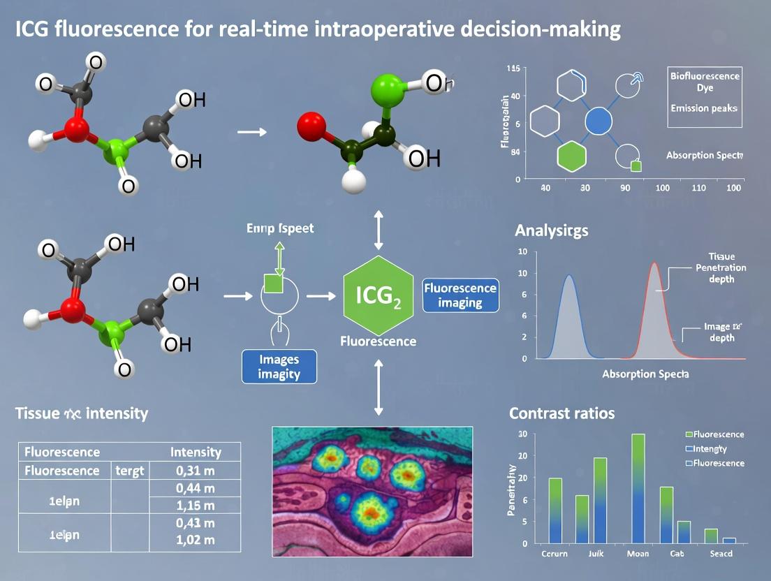
Indocyanine Green (ICG) fluorescence imaging has evolved from a vascular imaging tool into a transformative platform for real-time intraoperative decision-making across surgical and drug development fields.
ICG Fluorescence Imaging: Revolutionizing Real-Time Surgical Decision-Making and Precision Medicine
Abstract
Indocyanine Green (ICG) fluorescence imaging has evolved from a vascular imaging tool into a transformative platform for real-time intraoperative decision-making across surgical and drug development fields. This article provides a comprehensive analysis for researchers and drug development professionals, covering the foundational science of ICG's pharmacokinetics and targetable biological pathways. It details advanced methodological applications in oncology, perfusion assessment, and nerve visualization, alongside protocols for dye administration and imaging systems. The content addresses critical troubleshooting of technical and biological variables affecting signal fidelity and offers optimization strategies. Finally, it presents a rigorous validation framework, comparing ICG to alternative fluorophores and hybrid techniques while reviewing clinical trial evidence and cost-benefit analyses. This synthesis highlights ICG's pivotal role in advancing surgical precision, patient outcomes, and the development of targeted therapeutic and diagnostic agents.
The Science of ICG: Pharmacokinetics, Mechanisms, and Targetable Biological Pathways
This whitepaper provides the foundational chemical and pharmacokinetic data essential for the broader thesis research on "Optimizing ICG Fluorescence for Real-Time Intraoperative Decision-Making." Precise understanding of ICG's molecular behavior, distribution, and clearance is critical for standardizing administration protocols, interpreting fluorescent signals, and developing quantitative imaging algorithms for surgical guidance.
Chemical Properties of ICG
Indocyanine green (ICG) is a water-soluble, anionic tricarbocyanine dye. Its core structure is a polycyclic system with conjugated double bonds, responsible for its near-infrared (NIR) absorption and fluorescence.
Key Physicochemical Parameters
- Molecular Formula: C₄₃H₄₇N₂NaO₆S₂
- Molecular Weight: 774.96 g/mol (sodium salt)
- Optical Properties: Maximum absorption: 780-810 nm in aqueous media/plasma. Maximum fluorescence emission: 820-850 nm.
- Hydrophilicity/Lipophilicity: Amphiphilic; contains hydrophobic aromatic regions and hydrophilic sulfonate groups.
- Protein Binding: >95% binds to plasma proteins, primarily albumin and α₁-lipoproteins.
Stability and Handling
ICG is light-sensitive and susceptible to aqueous degradation, particularly under thermal stress. It must be reconstituted with aqueous solvent (e.g., sterile water) immediately before use. Aqueous solutions are unstable and should be used within a few hours.
Table 1: Summary of Key Chemical Properties of ICG
| Property | Specification | Research Implication |
|---|---|---|
| Primary Absorption (λmax) | ~800 nm in plasma | Defines optimal excitation laser wavelength. |
| Primary Emission (λmax) | ~830 nm in plasma | Informs emission filter selection for cameras. |
| Molar Extinction Coefficient | ~1.3 x 10⁵ M⁻¹cm⁻¹ in plasma | High absorption enables low-dose detection. |
| Quantum Yield in Blood | ~0.028 (2.8%) | Low yield necessitates sensitive detectors. |
| Plasma Protein Binding | >95% (Albumin) | Determines vascular confinement and pharmacokinetics. |
Pharmacokinetic Profile: From Injection to Clearance
Following intravenous injection, ICG undergoes a well-characterized pharmacokinetic journey.
Experimental Protocol for Basic PK Study: To determine standard PK parameters, administer a bolus IV injection of ICG (common dose: 0.1-0.5 mg/kg) to an animal model or human subject. Collect serial blood samples over 60 minutes. Measure plasma ICG concentration via fluorescence spectrophotometry or HPLC. Analyze data using non-compartmental methods.
Distribution Phase
Immediately post-injection, ICG binds rapidly to plasma proteins. This confines it primarily to the intravascular space, making it an effective blood pool agent for angiography. Extravasation occurs in tissues with increased vascular permeability (e.g., tumors, inflammation).
Metabolism and Hepatic Clearance
ICG is not metabolized. It is taken up exclusively by hepatocytes via organic anion-transporting polypeptides (OATP1B1/1B3) and excreted unchanged into the bile via multidrug resistance-associated protein 2 (MRP2).
Excretion and Elimination
ICG undergoes rapid hepatobiliary excretion, with no renal elimination or enterohepatic recirculation. It is ultimately excreted in feces.
Table 2: Summary of Key Pharmacokinetic Parameters of ICG in Humans
| Parameter | Typical Value/Range | Notes & Variability |
|---|---|---|
| Plasma Half-life (t₁/₂) | 3-5 minutes | Highly dependent on hepatic function and blood flow. |
| Plasma Clearance Rate | 0.14-0.23 L/min | Decreases significantly in liver dysfunction. |
| Volume of Distribution (Vd) | ~0.05 L/kg (~3.5 L in 70kg adult) | Approximates plasma volume, confirming vascular confinement. |
| Primary Excretion Route | Biliary (>95%) | No meaningful urinary excretion. |
| Time to Peak Hepatic Uptake | ~15-20 minutes post-injection | Informs timing for liver function tests. |
Experimental Protocol for Hepatic Uptake Imaging: In a murine model, administer ICG IV. Use a NIR fluorescence imaging system to capture sequential ventral images over 60 minutes. Regions of interest (ROIs) are drawn over the liver and background. The kinetics of liver accumulation and subsequent biliary clearance can be quantified by plotting mean fluorescence intensity (MFI) over time.
Visualizing ICG Pharmacokinetics and Pathways
Title: ICG Pharmacokinetic Pathway from Injection to Clearance
Title: Experimental Workflow for ICG Imaging in Surgical Research
The Scientist's Toolkit: Key Research Reagent Solutions
Table 3: Essential Materials for ICG-Based Fluorescence Research
| Item / Reagent Solution | Function & Research Purpose |
|---|---|
| Lyophilized ICG Powder | The core NIR fluorophore. Must be high purity (>95%) and from a reliable source (e.g., diagnostic or pharmaceutical grade) for reproducible results. |
| Sterile Water for Injection | The recommended reconstitution solvent. Preserves isotonicity and avoids precipitation or aggregation that can occur with saline. |
| Albumin Solution (e.g., HSA) | Used in in vitro studies to simulate plasma conditions, stabilizing ICG and defining its optical properties in a physiological environment. |
| Standardized NIR Fluorescence Phantom | Contains channels or wells with known ICG concentrations. Critical for calibrating imaging systems, validating sensitivity, and enabling quantitative intensity comparisons. |
| Precision Syringe Pumps | For controlled, reproducible intravenous infusion in animal studies, allowing for precise kinetic studies and modeling of different administration protocols. |
| HPLC System with Fluorescence Detector | For quantifying ICG concentration in plasma/tissue homogenates with high specificity, separating ICG from potential metabolites or degradation products. |
| Commercial NIR Imaging System | Integrated hardware/software platform (e.g., from PerkinElmer, LI-COR, KARL STORZ, Hamamatsu) providing controlled excitation, sensitive emission detection, and analysis tools for in vivo studies. |
| Tissue Homogenization Kit | For extracting ICG from excised tissues post-imaging to correlate in vivo fluorescence signals with ex vivo quantitative drug content. |
1. Introduction This whitepaper delineates the fundamental biophysical and physiological mechanisms governing the generation of fluorescence signal and tissue contrast, with a specific focus on agents like Indocyanine Green (ICG). Framed within the broader thesis of advancing ICG fluorescence for real-time intraoperative decision-making, understanding these core principles is paramount for optimizing imaging protocols, interpreting surgical field data, and developing next-generation contrast agents. The mechanisms of the Enhanced Permeability and Retention (EPR) effect, plasma protein binding, and cellular uptake collectively determine the spatial distribution, temporal kinetics, and ultimate signal-to-background ratio critical for surgical guidance.
2. The Enhanced Permeability and Retention (EPR) Effect The EPR effect is a cornerstone phenomenon enabling the passive targeting of macromolecular agents and nanoparticles to pathological tissues, particularly tumors.
- Mechanism: Tumor vasculature is characterized by aberrant architecture, wide fenestrations (gaps between endothelial cells), and poor lymphatic drainage. This allows molecules and particles of a specific size range (~10-200 nm) to extravasate from the bloodstream into the tumor interstitium and be retained there.
- Quantitative Parameters: The efficiency of the EPR effect is influenced by multiple variables, as summarized in Table 1.
Table 1: Key Quantitative Parameters Influencing the EPR Effect
| Parameter | Typical Range/Value in Tumors | Impact on Contrast Agent Accumulation |
|---|---|---|
| Vascular Pore Size | 100-780 nm | Determines maximum particle size for extravasation. |
| Cut-off Size (Ps80) | ~400-600 nm | Effective pore size for liposomes/particles. |
| Interstitial Fluid Pressure (IFP) | 5-40 mmHg (vs. ~0 in normal tissue) | High IFP at tumor core hinders convective inflow, leading to heterogeneous distribution. |
| Plasma Half-life | Minutes to Hours | Longer circulation increases exposure to leaky vasculature. |
| Molecular Weight Cut-off | > ~40 kDa | Threshold for significant retention via EPR. |
- Experimental Protocol for Assessing EPR:
- Agent Preparation: A fluorescent nanoparticle (e.g., 100 nm diameter) labeled with a dye such as ICG or a near-infrared (NIR) fluorophore (e.g., Cy5.5) is synthesized and characterized.
- Animal Model: Implant a subcutaneous tumor (e.g., murine CT26 colon carcinoma) in a rodent model.
- Administration & Circulation: Intravenously inject the nanoparticle formulation via the tail vein at a standardized dose (e.g., 2 mg/kg nanoparticle equivalent).
- In Vivo Imaging: Use a fluorescence molecular tomography (FMT) or an intraoperative imaging system at multiple time points (e.g., 1, 4, 24, 48 hours) to quantify tumor-associated fluorescence signal.
- Ex Vivo Validation: At terminal time points, harvest tumors and major organs (liver, spleen, kidneys, lungs, heart). Homogenize tissues, extract the fluorophore, and quantify fluorescence intensity using a plate reader to calculate % injected dose per gram (%ID/g) of tissue.
- Histology: Confirm nanoparticle localization in tumor sections using fluorescence microscopy.
Diagram 1: The EPR Effect Pathway
3. Plasma Protein Binding For small-molecule fluorophores like ICG, interaction with plasma proteins is a primary determinant of biodistribution and fluorescence properties.
- Mechanism: ICG, upon intravenous injection, rapidly and extensively (>95%) binds to plasma proteins, primarily albumin and α1-lipoproteins. This binding:
- Prevents rapid renal clearance, extending plasma half-life to 2-4 minutes in humans.
- Shifts its absorption/emission spectrum slightly.
- Quenches fluorescence in the bound state, which is partially relieved upon extravasation or interaction with cellular membranes, contributing to contrast.
- Dictates its hydrodynamic size, effectively creating an ~7 nm protein-dye complex that influences its vascular permeability.
Table 2: Impact of ICG-Protein Binding
| Property | Free ICG | Protein-Bound ICG | Consequence for Imaging |
|---|---|---|---|
| Primary Carrier | N/A | Albumin, α1-lipoprotein | Determines pharmacokinetics. |
| Fluorescence Quantum Yield | Low | Very Low (Quenched) | Blood pool signal is dim. |
| Plasma Half-life | Seconds | 2-4 min | Brief imaging window. |
| Effective Size | ~1.2 nm | ~7 nm | Limited extravasation in normal tissues; leaks via EPR. |
- Experimental Protocol for Studying Protein Binding:
- Sample Preparation: Prepare solutions of ICG (e.g., 10 µM) in phosphate-buffered saline (PBS) and in PBS containing 4% human serum albumin (HSA) or 100% fetal bovine serum (FBS).
- Spectroscopic Analysis: Record absorption spectra (600-900 nm) and fluorescence emission spectra (excitation ~780 nm, emission 800-850 nm) for both solutions.
- Fluorescence Quenching Assay: Titrate a fixed concentration of ICG with increasing concentrations of HSA. Measure fluorescence intensity and fit data to a binding isotherm (e.g., Langmuir) to calculate binding affinity (Kd).
- Size-Exclusion Chromatography (SEC): Load the ICG-HSA mixture onto an SEC column coupled with UV-Vis and fluorescence detectors. Elute with PBS and monitor co-elution of the protein (UV 280 nm) and ICG (absorbance ~780 nm or fluorescence) to confirm complex formation and determine its apparent molecular weight.
4. Cellular Uptake Cellular internalization of fluorescent agents can provide additional contrast by labeling specific cell populations (e.g., macrophages, tumor cells).
- Mechanisms: Uptake can occur via:
- Passive Diffusion: For small, lipophilic molecules.
- Endocytosis: The primary route for nanoparticles and protein complexes. This includes pinocytosis, receptor-mediated endocytosis (e.g., via albumin receptors), and phagocytosis (by immune cells).
- Impact on Contrast: Cellular uptake can lead to signal retention within tissues, potentially improving target-to-background ratio over time. However, non-specific uptake by macrophages in the liver and spleen (reticuloendothelial system, RES) can sequester agents and reduce target availability.
Diagram 2: Cellular Uptake Pathways
5. Synthesis for Intraoperative Imaging In the context of intraoperative ICG fluorescence imaging:
- Early Phase (1-5 min post-injection): Contrast is dominated by vascular flow and protein-bound ICG, highlighting vasculature and hypervascular tumors.
- Intermediate Phase (5-60 min): The EPR effect becomes dominant. Protein-bound ICG extravasates through leaky tumor vasculature, providing a "bulk tumor" signal. Some cellular uptake may begin.
- Late Phase (>1-24 hours): ICG is cleared hepatically. Residual contrast may arise from ICG retained in tumor stroma or within tumor-associated macrophages. Non-specific uptake in the RES is a key background consideration.
Diagram 3: ICG Imaging Phase Timeline
6. The Scientist's Toolkit: Research Reagent Solutions
Table 3: Essential Materials for Investigating Fluorescence Mechanisms
| Item | Function/Application | Example |
|---|---|---|
| ICG (Indocyanine Green) | The foundational NIR-I fluorophore for clinical and preclinical imaging. | Akorn NDC 17478-701-10; Diagnostic Green |
| Human Serum Albumin (HSA) | To study protein binding kinetics, spectral shifts, and to create protein-sized complexes. | Sigma-Aldrich A1653; Fatty acid-free. |
| NIR Fluorescent Nanoparticles | To model and study the EPR effect with controlled size and surface chemistry. | 100 nm fluorescent polystyrene beads (e.g., from Spherotech); Liposomes loaded with ICG. |
| Fluorescence Plate Reader | For high-throughput quantification of fluorescence in tissue homogenates or in vitro assays. | Tecan Spark; BioTek Cytation. |
| Small Animal Imaging System | For longitudinal, non-invasive tracking of fluorescence biodistribution and kinetics in vivo. | PerkinElmer IVIS; Medtronic FLUOBEAM (clinical). |
| Size-Exclusion Chromatography (SEC) Columns | To separate and analyze protein-fluorophore complexes by hydrodynamic size. | Superdex 200 Increase; TSKgel G3000SW. |
| Tumor Cell Lines & Animal Models | To create physiologically relevant models for studying EPR and uptake in vivo. | Murine models: CT26, 4T1; Rat models: 9L glioma. |
| Fluorescence Microscope with NIR Detector | For cellular and subcellular localization of fluorophores in tissue sections. | Confocal microscope with PMT detectors capable of 800+ nm emission. |
Abstract: In the development and application of indocyanine green (ICG) fluorescence for real-time intraoperative guidance, a precise understanding of its interaction with specific biological targets is paramount. This technical guide delineates the core molecular and physiological mechanisms of angiogenesis, vascular permeability, and lymphatic drainage. These processes govern the pharmacokinetics of ICG, its accumulation in target tissues, and its utility as a surgical beacon. Mastery of these targets enables researchers to optimize imaging protocols, interpret fluorescence signals accurately, and develop next-generation conjugates for enhanced specificity in oncologic, reconstructive, and lymphatic surgery.
Angiogenesis: The Vascular Supply Pathway
Angiogenesis, the formation of new blood vessels from pre-existing vasculature, is a hallmark of cancer and wound healing. Tumors secrete pro-angiogenic factors to establish a nutrient supply, creating vasculature that is chaotic, leaky, and overexpressed in specific molecular markers. ICG, when administered intravenously, binds to plasma proteins (primarily albumin) and is delivered via this abnormal vasculature, allowing for tumor demarcation.
Key Signaling Pathway (VEGF-VEGFR2): The Vascular Endothelial Growth Factor (VEGF)-A signaling through VEGFR2 is the predominant driver of pathological angiogenesis.
Title: VEGF-VEGFR2 Signaling in Angiogenesis
Quantitative Data on Tumor Vasculature: Table 1: Characteristics of Tumor Vasculature vs. Normal Vasculature
| Parameter | Normal Vasculature | Tumor Vasculature | Measurement Technique |
|---|---|---|---|
| Vessel Density | 200-400 vessels/mm² | 600-2000 vessels/mm² | CD31 immunohistochemistry |
| Pericyte Coverage | High (>70%) | Low, aberrant (<30%) | α-SMA/CD31 co-staining |
| Inter-vessel Distance | Regular (~40-60 µm) | Irregular, highly variable (10-200 µm) | Multiphoton microscopy |
| Blood Flow Rate | Consistent (∼1-5 mm/s) | Heterogeneous, often stagnant (0-2 mm/s) | Doppler ultrasound / IVM |
| Hypoxic Fraction (pO₂) | > 25 mmHg | < 10 mmHg (in regions) | Hypoxyprobe staining |
Experimental Protocol: In Vivo Angiogenesis Assay (Matrigel Plug)
- Materials: Growth-factor reduced Matrigel, pro-angiogenic factor (e.g., VEGF, bFGF), heparin, ICG (optional for imaging).
- Procedure: Mix Matrigel (∼500 µL) with angiogenic factors. Subcutaneously inject into the flanks of anesthetized mice (e.g., C57BL/6).
- ICG Imaging: After 7-14 days, inject ICG (2.5 mg/kg, i.v.). Use a fluorescence imaging system (e.g., PerkinElmer IVIS, FLARE surgery system) to quantify fluorescence intensity within the plug ex vivo or via transdermal imaging.
- Endpoint Analysis: Harvest plugs, digest, and analyze by flow cytometry (CD31+/CD45- endothelial cells) or measure hemoglobin content (Drabkin’s reagent).
Vascular Permeability: The Enhanced Permeability and Retention (EPR) Effect
The EPR effect is the cornerstone of passive tumor targeting. Pathological angiogenesis produces vessels with compromised integrity due to poorly formed adherens junctions and reduced pericyte coverage. This hyperpermeability, combined with ineffective lymphatic drainage, leads to the accumulation of macromolecules like ICG-albumin complexes (∼7 nm hydrodynamic radius) within the tumor interstitial space.
Key Signaling Pathway (VEGF-Induced Permeability): VEGF-A directly induces endothelial cell contraction and junctional disassembly via Src kinase.
Title: VEGF-Induced Vascular Hyperpermeability Pathway
Quantitative Data on the EPR Effect: Table 2: Pharmacokinetic Parameters of ICG in Tumors via EPR
| Parameter | Value Range (Tumor) | Value Range (Normal Tissue) | Implication for ICG Imaging |
|---|---|---|---|
| Plasma Half-life (ICG-Albumin) | 2-4 minutes | 2-4 minutes | Rapid clearance requires precise timing. |
| Tumor Accumulation Peak | 10-60 minutes post-injection | N/A | Optimal imaging window. |
| Permeability Coefficient (P) | 10-50 x 10⁻⁷ cm/s | 0.5-2 x 10⁻⁷ cm/s | Direct measure of "leakiness." |
| Tumor-to-Background Ratio (TBR) | 2.0 - 8.0 (varies by model) | 1.0 (baseline) | Key metric for surgical visibility. |
Experimental Protocol: Measuring Vascular Permeability (Evans Blue Assay)
- Materials: Evans Blue dye (0.5% in saline), formamide, mouse tumor model (e.g., subcutaneous LLC, 4T1).
- Procedure: Inject Evans Blue (4 mL/kg, i.v.) via tail vein. Allow circulation for 30-60 minutes. Perfuse animal with saline via cardiac puncture to clear intravascular dye.
- Sample Processing: Harvest tumor and contralateral normal tissue (e.g., muscle). Weigh tissues, incubate in formamide (1 mL/100 mg tissue) at 55°C for 24h.
- Quantification: Centrifuge formamide extract. Measure absorbance of supernatant at 620 nm (reference 740 nm). Calculate µg Evans Blue/mg tissue from a standard curve.
Lymphatic Drainage: The Clearance and Mapping Pathway
The lymphatic system is responsible for fluid homeostasis and immune surveillance. Tumors can induce lymphangiogenesis (formation of new lymphatic vessels) to facilitate metastasis. ICG binds to interstitial proteins and is actively taken up by initial lymphatic capillaries, providing a robust method for real-time lymphatic mapping and sentinel lymph node (SLN) biopsy.
Key Signaling Pathway (VEGF-C/VEGFR3 in Lymphangiogenesis):
Title: VEGF-C/VEGFR3 Lymphangiogenesis Signaling
Quantitative Data on ICG in Lymphatic Mapping: Table 3: ICG Performance in Sentinel Lymph Node Biopsy (Clinical Metrics)
| Parameter | Breast Cancer | Melanoma | Gynecologic Cancers | Notes |
|---|---|---|---|---|
| ICG Dose (Intradermal/Peritumoral) | 0.5 - 2.5 mg/mL (0.1-1 mL) | 0.5 - 1.0 mg/mL | 0.5 - 2.5 mg/mL | Concentration varies by institution. |
| Time to SLN Visualization | 1-5 minutes | 1-3 minutes | 3-10 minutes | Depends on injection site depth. |
| Detection Rate (ICG vs. Radioisotope) | 95-100% | 98-100% | 92-98% | Often combined for highest accuracy. |
| Number of SLNs Identified | 1-3 (average) | 1-4 (average) | 1-6 (average) | ICG may identify more distal nodes. |
Experimental Protocol: Real-Time ICG Lymphatic Mapping (Rodent)
- Materials: ICG (0.5-1.0 mg/mL in saline), near-infrared fluorescence imaging system, rodent model (e.g., mouse hind limb, ear).
- Procedure: Anesthetize animal. Inject 10-20 µL of ICG solution intradermally at the target site (e.g., footpad, periareolar).
- Imaging: Immediately begin dynamic imaging (e.g., 1 frame/sec for 10 min). Observe the formation of lymphatic capillaries, collecting vessels, and SLN filling.
- Quantification: Measure time-to-first-SLN, lymphatic vessel length, and fluorescence intensity kinetics in the SLN over time.
The Scientist's Toolkit: Research Reagent Solutions
Table 4: Essential Reagents and Materials for ICG-Angio/Lymphatic Research
| Item | Function / Application | Example Product / Model |
|---|---|---|
| ICG (Indocyanine Green) | Near-infrared fluorophore for vascular/lymphatic imaging. | Akorn IC-Green, Pulsion ICG |
| Albumin, Human or BSA | To pre-bind ICG for studying EPR effect dynamics. | Sigma-Aldrich A9731 |
| Recombinant VEGF-A | Induce angiogenesis and hyperpermeability in in vitro & in vivo models. | PeproTech 100-20 |
| Recombinant VEGF-C | Stimulate lymphangiogenesis in experimental models. | R&D Systems 2179-VC |
| VEGFR2 (Kinase Inhibitor) | Pharmacologically inhibit angiogenesis to study ICG uptake modulation. | SU1498 (Sigma), Apatinib |
| Anti-CD31 Antibody | Immunohistochemical staining for vascular endothelial cells (angiogenesis quantification). | BD Biosciences 553370 |
| Anti-LYVE-1 Antibody | Immunohistochemical staining for lymphatic endothelial cells. | R&D Systems AF2125 |
| Matrigel (Growth Factor Reduced) | Substrate for in vitro tube formation and in vivo plug assays. | Corning 356231 |
| Fluorescence Imaging System | Real-time in vivo and ex vivo quantification of ICG signal. | PerkinElmer IVIS, Medtronic SPY |
| Fluorophore-Conjugated Dextrans | To measure vascular permeability (size-dependent leakage). | Texas Red-dextran (70 kDa, Invitrogen) |
| Lymphatic-Specific Reporter Mouse | Genetic model for visualizing lymphatic vessels (e.g., Prox1-GFP). | Jackson Labs Stock #012429 |
The Evolution from Vascular Tracer to Tumor-Targeting and Functional Imaging Agent
Within the broader thesis on the optimization of Indocyanine Green (ICG) fluorescence for real-time intraoperative decision-making, this whitepaper examines the fundamental shift in the application of fluorescent agents. ICG's journey from a nonspecific vascular and biliary tracer to a platform for tumor-targeted and functional imaging encapsulates a pivotal trend in oncologic surgery and drug development. This evolution is driven by the need to move beyond simple tissue perfusion assessment toward specific molecular recognition of tumor margins, sentinel lymph nodes, and critical functional structures, thereby providing surgeons with biologically relevant visual guidance.
The Evolutionary Pathway: Core Mechanisms and Targets
The transition hinges on three principal strategies: passive accumulation via the Enhanced Permeability and Retention (EPR) effect, active targeting through conjugation to biomolecules, and activation by tumor-specific enzymes.
Table 1: Comparative Analysis of ICG-Based Imaging Agents
| Agent Type | Example Formulation | Primary Target/Mechanism | Tumor-to-Background Ratio (TBR)* | Optimal Imaging Window (Post-Injection) | Key Limitation |
|---|---|---|---|---|---|
| Free ICG (Vascular) | ICG in aqueous solution | Blood vessels, EPR | 1.5 - 2.5 | 0 - 30 mins | Rapid clearance, nonspecific |
| Passive Nano-ICG | ICG-loaded liposomes | Tumor vasculature (EPR) | 3.0 - 4.5 | 6 - 24 hours | Batch variability, liver sequestration |
| Active Targeted | Anti-EGFR-ICG conjugate | Epidermal Growth Factor Receptor | 4.0 - 8.0 | 24 - 72 hours | Immunogenicity, complex manufacturing |
| Enzyme-Activatable | MMP-9 substrate-ICG | Matrix Metalloproteinase-9 | 8.0 - 15.0 (upon activation) | 24 - 48 hours | Substrate specificity, background hydrolysis |
*TBR values are representative ranges from preclinical studies and can vary significantly with tumor model and pharmacokinetics.
Table 2: Clinical-Stage Tumor-Targeting ICG Derivatives (Selected)
| Agent Name | Developer/Institution | Phase | Indication | Key Differentiator |
|---|---|---|---|---|
| OTL38 | On Target Laboratories | Phase III (Approved) | Folate receptor-α+ ovarian cancer | Folate-ICG conjugate for precise tumor margin delineation. |
| BLZ-100 (Tozuleristide) | Blaze Bioscience | Phase II/III | Pediatric CNS tumors | Chlorotoxin-ICG peptide targeting matrix metalloproteinase-2. |
| SGM-101 | SurgiMab | Phase II | Colorectal cancer | Anti-CEA antibody-ICG conjugate for colorectal metastases. |
Experimental Protocols for Key Validations
Protocol 1: Evaluating Passive Accumulation via EPR
Objective: To quantify the enhanced tumor accumulation of nano-formulated ICG vs. free ICG. Materials: See "The Scientist's Toolkit" below. Method:
- Animal Model: Implant subcutaneous xenografts (e.g., HT-29 colorectal) in nude mice (n=5/group).
- Agent Administration: Inject via tail vein: Group A (Free ICG, 0.1 mg/kg), Group B (ICG-Liposomes, equivalent dose).
- Longitudinal Imaging: Use a small animal fluorescence imaging system (e.g., PerkinElmer IVIS). Acquire images at 5 min, 30 min, 2h, 6h, 24h, and 48h post-injection (Ex: 745 nm, Em: 820 nm).
- Ex Vivo Analysis: Euthanize animals at peak TBR (typically 24h for liposomes). Excise tumors and major organs (liver, spleen, kidneys, lungs, muscle). Measure fluorescence intensity of each tissue homogenate.
- Data Analysis: Calculate TBR as (Fluorescence intensity per gram tumor) / (Fluorescence intensity per gram muscle). Perform statistical comparison (Student's t-test) between groups.
Protocol 2: Validating Active Targeting Specificity
Objective: To confirm receptor-mediated uptake of a targeted ICG conjugate using a blocking study. Materials: Targeted agent (e.g., Anti-EGFR-ICG), excess unlabeled blocking antibody (e.g., Cetuximab). Method:
- Pre-Blocking Group: Administer a 100-fold molar excess of unlabeled anti-EGFR antibody intravenously 1 hour prior to Anti-EGFR-ICG injection.
- Test Group: Administer Anti-EGFR-ICG alone (0.15 mg/kg).
- Control Group: Administer an Isotype-Control-ICG conjugate.
- Imaging & Analysis: Image at 24h and 48h. Compare mean fluorescence intensity in tumors across groups using one-way ANOVA. Specific binding is confirmed if signal in the pre-blocked group is significantly reduced to the level of the isotype control.
The Scientist's Toolkit: Essential Research Reagents & Materials
Table 3: Key Reagents for Developing/Testing Tumor-Targeting ICG Agents
| Item | Function & Rationale | Example Product/Catalog |
|---|---|---|
| ICG, Premium Grade | Core fluorophore for conjugation or encapsulation. High purity is critical for reproducible pharmacokinetics. | BioVision, #1966; Sigma-Aldrich, 12633 |
| Heterobifunctional Crosslinkers | For covalent conjugation of ICG to targeting moieties (e.g., antibodies, peptides). Control linker length and chemistry. | Succinimidyl ester-maleimide (SMCC) linkers (Thermo Fisher, 22322). |
| Nanocarrier Kits | For passive targeting studies. Liposomes, PLGA nanoparticles, or micelles to enhance EPR effect. | FormuMax Scientific ICG-Liposome Kit; PolySciTech PLGA. |
| Fluorescence Quenchers | For constructing enzyme-activatable probes. Quenches ICG fluorescence until cleaved. | Black Hole Quencher-3 (BHQ-3) (Biosearch Tech). |
| Recombinant Target Proteins | For in vitro binding affinity validation (e.g., SPR, ELISA). | Recombinant human EGFR (R&D Systems, 1095-ER). |
| Fluorescence Imaging System | For longitudinal, quantitative in vivo imaging. Must have NIR capabilities. | PerkinElmer IVIS Spectrum; LI-COR Pearl. |
| Cell Lines with Target Expression | Positive and negative controls for in vitro and in vivo studies. | EGFR+: A431; FolateR+: KB; Control: MCF-10A. |
Current Regulatory Status and Approved Clinical Indications for ICG
This whitepaper provides an in-depth analysis of the regulatory landscape and approved clinical uses of Indocyanine Green (ICG), framed within the ongoing research on its fluorescence for real-time intraoperative decision-making. ICG’s unique pharmacokinetic and fluorescent properties have enabled its expansion beyond traditional diagnostic angiography into a critical tool for surgical guidance.
ICG’s regulatory approval varies by region and application, evolving from an intravenous diagnostic agent to an image-guided surgery enhancer.
Table 1: Global Regulatory Status Summary for ICG (as of 2024)
| Region/Authority | Primary Regulatory Classification | Key Approved Indication(s) | Status Notes |
|---|---|---|---|
| U.S. FDA | Diagnostic agent (Drug), Dye for medical imaging (Device) | Hepatic function assessment; cardiovascular and ophthalmic angiography; adjunct for lymph node, biliary, and perfusion imaging | Approved as a drug (1959) and as a component of NIR fluorescence imaging systems (e.g., PINPOINT). |
| EMA (Europe) | Diagnostic agent, Medical device component | Hepatic, cardiovascular, and ophthalmic diagnostics; sentinel lymph node mapping; visualization of anatomical structures | Approved nationally (e.g., Germany’s BfArM) and as part of CE-marked imaging systems. |
| PMDA (Japan) | Medicinal product, Reagent | Hepatic function, retinal angiography, cerebral blood flow measurement, sentinel lymph node mapping | Widely used; approvals for specific fluorescence-guided surgery applications exist. |
| NMPA (China) | Diagnostic drug | Retinal and choroidal angiography, hepatic function evaluation | Approved; use in fluorescence-guided surgery is an active research area. |
Approved Clinical Indications
The following table consolidates the major FDA-approved and widely recognized clinical indications for ICG.
Table 2: Detailed Approved Clinical Indications and Methodologies
| Approved Indication | Route of Administration | Core Methodology/Protocol Summary | Primary Mechanism |
|---|---|---|---|
| Hepatic Function & Cardiac Output | Intravenous bolus | Dye Dilution/Clearance Test: Administer 0.5 mg/kg ICG IV. Use densitometry or pulse spectrophotometry to measure plasma disappearance rate (PDR) and retention rate (ICG-R15). Normal PDR >18%/min. | Vascular dye binding to plasma proteins; hepatic clearance. |
| Ophthalmic Angiography | Intravenous bolus | Fundus Photography: Administer 25-50 mg ICG IV. Use a fundus camera with excitation (~805 nm) and emission (~835 nm) filters. Capture early (<1 min), mid (5-15 min), and late (>30 min) phase images. | Fluorescence from dye in choroidal and retinal vasculature. |
| Sentinel Lymph Node (SLN) Mapping | Interstitial (peritumoral, subdermal, subareolar) | Intraoperative Protocol: Prepare 1.25-5.0 mg/mL ICG solution. Inject 1-4 mL intraparenchymally. Use NIR fluorescence camera system (e.g., PINPOINT) to trace lymphatic ducts and identify fluorescent SLNs for biopsy. | Protein-binding dye transported via lymphatic vessels. |
| Biliary Tree Imaging | Intravenous (or direct cystic duct injection) | Cholangiography Protocol: Administer 2.5-10 mg ICG IV 30-60 min preoperatively. Use NIR fluorescence imaging to visualize extrahepatic bile ducts, identify anatomy, and assess for bile leaks. | Hepatocyte excretion into bile. |
| Perfusion Assessment (Plastic, Reconstructive, GI Surgery) | Intravenous bolus | Intraoperative Perfusion Imaging: Administer 5-10 mg ICG IV intraoperatively. Use NIR imaging to assess real-time tissue perfusion (e.g., bowel anastomoses, flaps). Time-to-fluorescence and intensity are key metrics. | Fluorescence in blood vessels after intravascular administration. |
Experimental Protocols for Research Validation
Protocol 1: Quantitative ICG Fluorescence for Tissue Perfusion Metrics
- ICG Preparation: Reconstitute 25 mg ICG in 10 mL sterile water (2.5 mg/mL). Protect from light.
- Animal/Subject Preparation: Establish physiological monitoring.
- Imaging System Calibration: Use a calibrated NIR fluorescence imaging system (e.g., FLARE, Quest Spectrum). Set excitation to 760±5 nm, emission collection to >810 nm.
- Dye Administration & Acquisition: Administer standardized IV bolus (e.g., 0.1 mg/kg). Start video acquisition pre-injection; continue for >5 minutes.
- Data Analysis: Use ROI analysis software. Calculate metrics: Time-to-peak (TTP), Maximum Intensity (Imax), Slope of fluorescence increase.
Protocol 2: Sentinel Lymph Node Mapping Efficacy Study
- Tracer Formulation: Dilute ICG in human serum albumin (HSA) to final 500 µM concentration.
- Injection: In a clinical trial setting, inject 1.0 mL intracutaneously around the tumor or areola.
- Imaging: Use an FDA-approved NIR imaging system. Document the first (“sentinel”) draining lymph node(s) visually and fluorescently.
- Validation: Excise all fluorescent and non-fluorescent but palpably suspicious nodes for histopathological analysis (H&E, immunohistochemistry).
- Endpoint Calculation: Determine sensitivity, specificity, and false-negative rate of ICG fluorescence vs. standard technique (radioisotope/blue dye).
Visualizing ICG Pathways and Experimental Workflows
Title: ICG Pharmacokinetic Pathways and Imaging Targets
Title: Standardized Workflow for ICG Fluorescence-Guided Surgery Research
The Scientist's Toolkit: Key Research Reagent Solutions
Table 3: Essential Materials for ICG Fluorescence Research
| Item | Function/Description | Example/Note |
|---|---|---|
| ICG, Sterile, USP Grade | The active fluorescent agent. Must be high purity for consistent pharmacokinetics. | PULSION (Diagnostic Green), IC-GREEN. |
| Near-Infrared (NIR) Imaging System | Captures ICG fluorescence (emission >810 nm). Critical for signal quantification. | FLARE, Quest Spectrum, PINPOINT (with SPY Fluorescence capability). |
| Albumin (HSA) Solution | Used to prepare stable ICG-HSA complexes, modulating lymphatic uptake and fluorescence yield. | 5% Human Serum Albumin. |
| Standardized Fluorescence Phantoms | For daily system calibration and quantification, ensuring inter-study reproducibility. | Solid phantoms with known ICG concentrations. |
| Data Acquisition & Analysis Software | Enables Region-of-Interest (ROI) analysis, kinetic curve fitting, and metric generation. | Custom (MATLAB, Python) or vendor-provided (e.g., Quest Research Suite). |
| Light-Opaque Vials & Tubing | Prevents photodegradation of ICG during preparation and administration. | Amber vials, foil wraps. |
| Physiological Monitoring Equipment | Correlates fluorescence kinetics with hemodynamic status (e.g., blood pressure, heart rate). | Essential for perfusion studies. |
Protocols in Practice: A Guide to ICG Administration, Imaging Systems, and Surgical Applications
Within the advancing field of image-guided surgery, Indocyanine Green (ICG) fluorescence has emerged as a pivotal tool for real-time intraoperative decision-making. The efficacy of this modality is fundamentally dependent on achieving optimal contrast at the target tissue, which is governed by the administered dosing protocol. This technical guide examines the core scientific debate between weight-based and fixed-dose administration strategies, and the critical variable of timing, to establish evidence-based standards for research and clinical translation in oncology, vascular, and reconstructive surgery.
Pharmacokinetic & Physicochemical Foundations of ICG
ICG is a water-soluble, amphiphilic tricarbocyanine dye. Upon intravenous injection, it rapidly and exclusively binds to plasma proteins, primarily albumin (>95%). This binding confines it to the intravascular space in normal vasculature, with a plasma half-life of 3-5 minutes. Clearance is exclusively hepatic, with biliary excretion. Fluorescence occurs in the near-infrared spectrum (peak emission ~830 nm) upon excitation (~780 nm), minimizing tissue autofluorescence and allowing deeper tissue penetration.
The achieved contrast is a function of:
- Dose: Total fluorophore molecules administered.
- Concentration: Local fluorophore density at the target.
- Timing: The phase of pharmacokinetic distribution (vascular, interstitial, clearance).
- Background: Non-specific uptake in surrounding tissue.
Weight-Based vs. Fixed-Dose Protocols: A Quantitative Analysis
The primary dosing strategies present distinct mechanistic rationales. Weight-based dosing aims to normalize the dose to the patient's plasma volume, theoretically leading to more predictable initial plasma concentrations. Fixed dosing simplifies protocols and may exploit the saturable nature of ICG-protein binding and physiological clearance pathways.
Table 1: Comparative Analysis of Dosing Strategies in Recent Literature
| Study & Year | Indication | Weight-Based Protocol | Fixed-Dose Protocol | Key Finding on Optimal Contrast |
|---|---|---|---|---|
| Matsui et al. (2021) | Hepatic Tumors | 0.5 mg/kg | 25 mg fixed | Fixed dose (25mg) provided superior and more consistent tumor-to-liver contrast due to saturation of hepatocyte receptors. |
| Schaafsma et al. (2023) | Sentinel Lymph Node (Breast) | 1.6 mL of 0.63 mM (variable mg) | 1.6 mL of 1.6 mM (fixed mg) | High fixed concentration (1.6 mM) yielded significantly higher signal-to-background ratio (SBR) in nodes independent of patient weight. |
| Grove et al. (2022) | Perfusion Assessment (Colorectal Anastomosis) | 0.1 mg/kg | 7.5 mg fixed | No significant difference in SBR; fixed dose recommended for procedural standardization. |
| Tseng et al. (2023) | Lymphatic Mapping (Endometrial Ca) | 0.5 mg/kg | 15 mg fixed | Weight-based dosing reduced inter-patient variability in time-to-first-signal detection for lymphatic mapping. |
Conclusion: The optimal strategy is indication-specific. Fixed-dose protocols appear superior for parenchymal tissue (liver) imaging and simple visualization, where saturation kinetics dominate. Weight-based dosing may be critical for dynamic, time-sensitive physiological mapping (lymphatics) where plasma concentration kinetics are paramount.
Timing Windows for Specific Clinical Indications
Timing is inextricably linked to the chosen dose and the biological target.
Table 2: Protocol Timing for Key Intraoperative Applications
| Clinical Goal | Recommended Dose | Administration-to-Imaging Timing | Pharmacokinetic Phase | Rationale |
|---|---|---|---|---|
| Angiography (Vessel Patency) | 5-10 mg fixed | Immediate (15-30 sec) | Intravascular (First Pass) | Maximizes contrast while ICG is confined to blood pool. |
| Sentinel Lymph Node Mapping | 1.6-10 mg fixed | Dynamic imaging for 10-20 min | Lymphatic Transit | Allows for uptake by lymphatics and transport to first-echelon nodes. |
| Tumor Delineation (Brain, Liver) | 25-50 mg fixed | 24 hours pre-op or intra-op after 1-2 hrs | Enhanced Permeability & Retention (EPR) | Allows extravasation in leaky tumor vasculature and clearance from normal parenchyma. |
| Perfusion Assessment (Anastomosis, Flap) | 0.1-0.3 mg/kg | Bolus: Immediate. Quantitative: 60-sec cine. | First Pass Kinetics | Analyzes inflow kinetics; low dose prevents signal saturation for quantitation. |
| Biliary Imaging | 2.5-5 mg fixed | 30-60 minutes pre-incision | Hepatobiliary Excretion | Allows hepatic uptake and excretion into bile ducts. |
Experimental Protocol for Dose-Timing Optimization
The following in vivo protocol is designed for researchers to systematically evaluate dosing variables.
Title: Quantitative Comparison of ICG Dosing Protocols in a Murine Window Chamber Model.
Objective: To determine the dose and time point that maximizes Signal-to-Background Ratio (SBR) for tumor vasculature imaging.
Materials:
- Animal Model: Athymic nude mouse with dorsal skinfold window chamber.
- Xenograft: Human cancer cell line (e.g., MDA-MB-231-GFP).
- ICG Formulation: Lyophilized powder, reconstituted in sterile water.
- Imaging System: NIR fluorescence microscope with 780 nm excitation and 830 nm emission filters.
- Software: ImageJ with quantitative fluorescence plugins.
Methodology:
- Tumor Implantation: Implant tumor cells into the window chamber. Allow growth until vascularized (~7-10 days).
- Dosing Cohorts: Randomize mice into groups (n=5/group):
- Group A: Fixed low dose (0.1 mg/mouse, ~5 mg/kg equivalent).
- Group B: Fixed high dose (0.5 mg/mouse, ~25 mg/kg equivalent).
- Group C: Weight-based dose (5 mg/kg).
- Imaging Timeline: For each mouse, acquire baseline autofluorescence image.
- Inject ICG via tail vein.
- Acquire sequential fluorescence images at: t = 30s, 1 min, 2 min, 5 min, 10 min, 30 min, 60 min, 24h.
- Image Analysis:
- Define Region of Interest (ROI): Tumor vessel hotspot.
- Define Background ROI: Adjacent normal tissue.
- Calculate Mean Fluorescence Intensity (MFI) for each ROI.
- Calculate SBR for each time point:
SBR = MFI_(Tumor) / MFI_(Background).
- Data Modeling: Plot SBR vs. Time for each group. Determine peak SBR and time-to-peak for each dosing strategy. Perform statistical comparison (ANOVA).
Visualization of Key Concepts
Diagram 1: ICG Pharmacokinetic Pathways to Contrast (100 chars)
Diagram 2: Dosing Protocol Decision Algorithm (100 chars)
The Scientist's Toolkit: Research Reagent & Material Solutions
Table 3: Essential Materials for ICG Fluorescence Research
| Item & Example | Function & Critical Specification |
|---|---|
| Lyophilized ICG (PZN-02913237) | The fluorophore. Must be high purity (>95%), stored desiccated, protected from light. Different vial sizes (5mg, 25mg, 50mg) enable flexible dosing. |
| Sterile Water for Injection (USP) | Reconstitution solvent. Must be sterile, non-buffered, and preservative-free to prevent ICG aggregation or quenching. |
| Human Serum Albumin (HSA) Solution | For in vitro binding studies. Simulates physiological protein binding to study fluorescence quantum yield and stability in plasma. |
| NIR Fluorescence Imaging System | Detection device. Must have matched laser/LED excitation (~780 nm) and sensitive NIR camera with appropriate emission filter (>820 nm). |
| Quantitative Analysis Software (e.g., ImageJ, LI-COR) | For calculating MFI, SBR, and pharmacokinetic curves. Requires capability to handle NIR image stacks and define dynamic ROIs. |
| Standardized Phantom (e.g., ICG in Intralipid) | For daily system calibration and sensitivity testing. Ensures inter-study reproducibility of fluorescence measurements. |
| In Vivo Animal Model with Window Chamber | Allows longitudinal, high-resolution visualization of ICG kinetics in tumor vasculature and interstitium. |
| Programmable Syringe Pump | Ensures precise, reproducible injection rates for kinetic studies, especially critical for first-pass analysis. |
This whitepaper provides a technical overview of commercial near-infrared (NIR) and indocyanine green (ICG) fluorescence imaging systems. The analysis is framed within the broader research thesis on leveraging ICG fluorescence for enhancing real-time intraoperative decision-making in oncological and vascular surgeries. The objective is to equip researchers and drug development professionals with the data necessary to select and utilize systems that can validate novel surgical guidance protocols and therapeutic agents.
Core Technical Specifications of Leading Commercial Systems
The following table summarizes the key quantitative specifications of prominent commercial NIR/ICG imaging systems, as gathered from current manufacturer data and peer-reviewed technical evaluations.
Table 1: Technical Specifications of Commercial NIR/ICG Imaging Systems
| System Name (Manufacturer) | Excitation Wavelength (nm) | Emission Detection (nm) | Field of View (cm) | Spatial Resolution | Frame Rate (fps) | ICG Detection Sensitivity (Minimum Concentration) | Form Factor |
|---|---|---|---|---|---|---|---|
| SPY-PHI (Stryker) | 806 | 826 - 876 | 20 x 20 | 1.5 mm at 15 cm | 30 | ~ 1 µM | Portable Cart |
| FLUOBEAM 800 (Fluoptics) | 785 ± 15 | 810 - 900 | 15 x 15 | 1.2 mm | 25 | 100 nM (in vitro claim) | Handheld / Cart |
| *Quest * (Quest Medical Imaging) | 760 - 785 | 800 - 850 | Variable (Lens-based) | 10 lp/mm (modulation) | 60 | < 10 nM (claimed) | Modular (Microscope/Camera) |
| PINPOINT (Novadaq/Stryker) | 805 | 835 | 18 x 14 | N/A | 60 | Low µM range | Laparoscopic / Open |
| IRIS (IRIScope) | 760 | 830 | N/A | Diffraction-limited | Real-time | N/A | Integrated with microscopes |
| HyperEye (Mizuho) | 760 | 820 | 10 x 15 | Sub-mm | 30 | ~ 5 µM | Surgical Microscope Integrated |
Detailed Experimental Protocol for System Validation
To contextualize these specifications within ICG research, a standard validation protocol is provided.
Protocol: Quantitative Validation of ICG Detection Limits for Intraoperative Imaging Systems
Objective: To determine the minimum detectable concentration (sensitivity) and linear dynamic range of an ICG fluorescence imaging system under simulated tissue conditions.
Materials:
- Commercial NIR/IICG imaging system (e.g., from Table 1).
- ICG powder (diagnostic grade).
- Serum albumin solution (1% w/v in PBS) or whole blood.
- PBS (Phosphate Buffered Saline).
- Black-walled 96-well plate or tissue-mimicking optical phantoms (Intralipid or India ink-based).
- Micropipettes and sterile tubes.
- Calibrated digital spectrometer (reference standard, optional).
Methodology:
- ICG Stock Solution: Prepare a 1 mM ICG stock solution in dimethyl sulfoxide (DMSO). Immediately dilute in 1% albumin/PBS to create a 100 µM working solution. Note: ICG is light-sensitive and unstable in aqueous solution; prepare fresh.
- Sample Series: Perform serial dilutions of the working solution in albumin/PBS to create concentrations spanning from 100 µM down to 0.1 nM (e.g., 100 µM, 10 µM, 1 µM, 100 nM, 10 nM, 1 nM, 0.1 nM).
- Background Control: Prepare control wells with albumin/PBS only.
- Phantom Setup: Dispense 200 µL of each concentration into separate wells of a black-walled plate. Alternatively, inject samples into channels within a tissue-mimicking phantom (scattering coefficient µs' ~ 1 mm⁻¹, absorption coefficient µa ~ 0.01 mm⁻¹) to simulate subcutaneous imaging.
- Image Acquisition: Position the imaging system at a standardized distance (e.g., 20 cm) and angle (90°) from the sample plane. Use manufacturer-recommended settings for ICG detection (typically "ICG mode"). Acquire images/video for each sample. Maintain consistent exposure time, gain, and laser power across all samples.
- Data Analysis: Use system-provided or third-party software (e.g., ImageJ) to measure mean fluorescence intensity (MFI) within a consistent region of interest (ROI) for each sample. Subtract the MFI of the background control.
- Calibration Curve: Plot Log(MFI) versus Log(ICG concentration). The lower limit of detection (LLOD) is typically defined as the concentration where MFI equals the background signal plus three standard deviations of the background. The linear range is the concentration span where the Log-Log plot remains linear (R² > 0.98).
Key Research Reagent Solutions Toolkit
Table 2: Essential Research Reagents and Materials for ICG Fluorescence Studies
| Item | Function in Research |
|---|---|
| Diagnostic Grade ICG | The FDA-approved fluorophore; used as the gold standard for perfusion assessment, lymphatic mapping, and as a comparator for new agents. |
| ICG-Labeled Targeting Agents (e.g., Antibodies, Peptides) | Enables molecular fluorescence imaging by targeting specific biomarkers (e.g., VEGF, CAIX) for tumor margin delineation. |
| Albumin (Human or BSA) | Stabilizes ICG in aqueous solution, prevents aggregation, and mimics in vivo protein-binding behavior. |
| Tissue-Mimicking Optical Phantoms | Calibrates imaging systems and validates penetration depth/signal recovery algorithms under controlled scattering and absorption conditions. |
| NIR Fluorescent Reference Standards | Stable, solid-state fluorescent slides or solutions used for daily system calibration and ensuring inter-study reproducibility. |
| Pharmacokinetic Modulators (e.g., Heparin) | Used in research to alter ICG clearance rates, enabling extended imaging windows for procedural guidance. |
Visualizing the ICG Workflow and Signaling in Research
The following diagrams, created using Graphviz DOT language, illustrate the core experimental workflow and the biological signaling pathway relevant to targeted ICG applications.
Diagram 1: ICG Fluorescence Research Workflow for Intraop Guidance
Diagram 2: ICG Biodistribution and Targeted Imaging Signaling
This whitepaper details advanced methodologies for intraoperative oncologic guidance, framed within a broader research thesis on Indocyanine Green (ICG) fluorescence for real-time surgical decision-making. The convergence of real-time tumor margin delineation and sentinel lymph node (SLN) mapping represents a paradigm shift in oncologic surgery, aiming to improve oncologic outcomes while preserving healthy tissue.
Technical Foundations: ICG Fluorescence Imaging
Indocyanine Green is a near-infrared (NIR) fluorophore (excitation ~780 nm, emission ~820 nm). Its utility in oncology stems from two primary mechanisms: the Enhanced Permeability and Retention (EPR) effect for passive tumor accumulation, and lymphatic drainage for SLN mapping. When administered intravenously, ICG extravasates through leaky tumor vasculature, delineating malignant tissue. When administered peritumorally, it drains via lymphatics to the first-echelon SLN.
Key Signaling and Pharmacokinetic Pathways
The following diagram illustrates the core pathways governing ICG-based tumor and SLN targeting.
Diagram 1: ICG Pathways for Tumor & SLN Targeting (98 chars)
Table 1: Clinical Performance Metrics of ICG-Guided Surgery (Recent Meta-Analysis Data)
| Cancer Type | Sensitivity for SLN Detection (%) | Specificity for SLN Detection (%) | Tumor-to-Background Ratio (TBR) Mean ± SD | Negative Predictive Value for Margins (%) |
|---|---|---|---|---|
| Breast Cancer | 95.2 - 99.8 | 95.0 - 100 | 3.5 ± 1.2 | 92.4 - 98.7 |
| Colorectal Cancer | 94.8 - 100 | 88.3 - 100 | 4.1 ± 1.8 | 89.5 - 96.2 |
| Head & Neck SCC | 86.5 - 98.3 | 90.1 - 99.5 | 2.8 ± 0.9 | 85.4 - 94.1 |
| Gastric Cancer | 97.1 - 100 | 91.2 - 100 | 3.9 ± 1.5 | 93.3 - 97.9 |
Table 2: ICG Administration Protocols for Dual Indication
| Application | ICG Dose | Administration Route | Injection Timing Pre-Op | Imaging System |
|---|---|---|---|---|
| Tumor Delineation | 5.0 - 10.0 mg/kg | Intravenous (IV) Bolus | 24 - 48 hours | PDE, FLARE, SPY-PHI |
| SLN Mapping | 0.5 - 2.5 mg/mL | Peritumoral, Intradermal | 5 - 30 minutes | Photodynamic Eye, IC-Flow |
| Combined Protocol | 5.0 mg/kg IV + | IV + Peritumoral | IV: 24h; PT: 15 min | Hybrid NIR/White Light Systems |
Detailed Experimental Protocols
Protocol A: Combined Tumor Delineation and SLN Mapping in Murine Models
Objective: To simultaneously evaluate primary tumor resection margins and lymphatic drainage in an orthotopic model.
Materials: See "The Scientist's Toolkit" below.
Procedure:
- Animal Model Preparation: Establish orthotopic tumor xenografts (e.g., 4T1 mammary carcinoma in BALB/c mice) and allow growth to ~100 mm³.
- ICG Administration for Tumor Delineation: Inject ICG intravenously at a dose of 5 mg/kg via tail vein 24 hours prior to imaging.
- Pre-operative Imaging: Anesthetize animal. Acquire baseline white-light and NIR fluorescence images using a calibrated imaging system (e.g., LI-COR Pearl or PerkinElmer IVIS). Calculate initial Tumor-to-Background Ratio (TBR).
- ICG Administration for SLN Mapping: Inject 10 µL of 1.0 mg/mL ICG solution in three peritumoral deposits.
- Real-Time Intraoperative Imaging:
- Perform dynamic lymphatic imaging for 10-15 minutes to identify draining lymphatic channels and the SLN.
- Mark the SLN location.
- Switch imaging mode to maximize tumor contrast. Use the fluorescence overlay to guide gross resection, aiming for a margin of normal tissue.
- Ex Vivo Analysis:
- Weigh and image the resected specimen. Confirm complete excision via ex vivo margin assessment.
- Excise the fluorescent SLN and submit for histopathological analysis (H&E, immunohistochemistry).
- Data Quantification:
- TBR:
(Mean Fluorescence Intensity of Tumor) / (Mean Fluorescence Intensity of Adjacent Normal Tissue) - SLN Detection Rate:
(Number of fluorescent SLNs identified) / (Total number of SLNs confirmed by histology) * 100 - Margin Status Correlation: Compare fluorescence at resection edge with histologic margin status (>2 mm clear).
- TBR:
Protocol B: Ex Vivo Human Specimen Margin Assessment
Objective: To validate ICG fluorescence against standard pathology for margin status in breast cancer lumpectomy specimens.
Procedure:
- Patient Dosing: Administer ICG (5 mg/kg IV) 24 hours prior to scheduled surgery.
- Specimen Handling: Immediately following lumpectomy, place the fresh, unfixed specimen on the imaging stage.
- Six-Sided Imaging: Acquire NIR fluorescence images from all six anatomical surfaces (anterior, posterior, medial, lateral, superior, inferior) with a fiducial marker for orientation.
- Image Analysis: Define a region of interest (ROI) on the brightest tumor area and on normal tissue from each surface. Calculate TBR for each surface.
- Pathology Correlation: The specimen is then inked according to standard protocol, sectioned, and processed for permanent histology. The surgeon's orientation is maintained.
- Statistical Analysis: A TBR threshold predictive of positive margin (<1 mm) is determined using Receiver Operating Characteristic (ROC) curve analysis.
The Scientist's Toolkit: Key Research Reagent Solutions
Table 3: Essential Materials for ICG Fluorescence Research
| Item / Reagent | Function / Role in Research | Example Vendor / Product Code |
|---|---|---|
| Indocyanine Green (ICG) | Near-infrared fluorophore; primary imaging agent for both tumor and lymphatic targeting. | PULSION Medical AG, Diagnostic Green |
| NIR Fluorescence Imaging System | Enables real-time visualization of ICG fluorescence; critical for intraoperative data capture. | LI-COR Pearl, Hamamatsu PDE, FLARE |
| Matrigel / Basement Membrane Matrix | For establishing orthotopic or invasive tumor models with relevant microenvironment. | Corning, #356231 |
| Tumor Cell Line (Luc2-tdTomato) | Expresses both bioluminescence (for tracking) and red fluorescence (for histology correlation). | ATCC, modified lines |
| ICG Conjugates (e.g., ICG-cRGD) | Targeted fluorophores for improved tumor specificity and retention. | LI-COR, custom synthesis services |
| Artificial Lymph Fluid | Buffer for in vitro testing of lymphatic uptake dynamics and particle stability. | Cellaria, #LY-001 |
| Tissue Clearing Agents (e.g., CUBIC) | For deep-tissue 3D imaging and analysis of tumor margins and lymphatic networks. | Tokyo Chemical Industry, #T3740 |
| Quantum Yield Reference Standard | Essential for calibrating imaging systems and ensuring quantitative, reproducible fluorescence data. | Starna Cells, NIR calibration sets |
Experimental Workflow for Dual-Modality Research
The following diagram outlines a standardized workflow integrating both research applications.
Diagram 2: Integrated Tumor & SLN Research Workflow (96 chars)
The integration of real-time tumor margin delineation and SLN mapping via ICG fluorescence constitutes a powerful tool for precision surgical oncology. The protocols and data presented herein provide a framework for rigorous research within a thesis focused on intraoperative decision-making. Future directions include the development of tumor-specific ICG conjugates, integration with hyperspectral imaging, and the application of artificial intelligence for predictive margin analysis and lymphatic pattern recognition.
This whitepaper provides an in-depth technical guide to perfusion assessment for anastomotic viability, framed within the context of a broader thesis on Indocyanine Green (ICG) fluorescence for real-time intraoperative decision-making. For researchers and drug development professionals, understanding and quantifying tissue perfusion is a critical step in validating novel therapeutics and surgical techniques aimed at reducing anastomotic failure—a major source of postoperative morbidity. ICG fluorescence imaging has emerged as the preeminent modality for real-time, quantitative perfusion assessment across surgical disciplines.
Core Principles of ICG Fluorescence Imaging
ICG is a near-infrared (NIR, excitation ~805 nm, emission ~835 nm) fluorophore that, when injected intravenously, binds to plasma proteins and remains intravascular. Its fluorescence, captured by specialized cameras, provides a dynamic map of blood flow. Quantitative analysis of the fluorescence signal allows for objective assessment of tissue perfusion, moving beyond subjective clinical evaluation.
Quantitative Parameters in Perfusion Assessment
The following table summarizes key quantitative parameters derived from ICG fluorescence time-intensity curves (TICs), their clinical significance, and associated experimental benchmarks.
Table 1: Key Quantitative Parameters from ICG Fluorescence Kinetics
| Parameter | Definition | Physiological Correlation | Typical Thresholds for Concern (Varies by Tissue/Bed) | Measurement Unit |
|---|---|---|---|---|
| Time-to-Peak (TTP) | Time from ICG bolus arrival to maximum fluorescence intensity. | Inversely related to arterial inflow. Delayed TTP indicates hypoperfusion. | > 60-90 seconds post-arterial clamp release (Colorectal). | Seconds (s) |
| Maximum Intensity (Imax) | Peak fluorescence intensity within the region of interest (ROI). | Correlates with blood volume in the microvasculature. | < 30% relative to well-perfused control tissue. | Arbitrary Fluorescence Units (AFU) or normalized % |
| Slope of Inflow (Rate of Rise) | Derivative of the initial upslope of the TIC. | Direct measure of blood flow velocity and arterial inflow. | Slope < 50% of control slope. | AFU/s or normalized %/s |
| T1/2 (Washout Half-Time) | Time for intensity to decay to half of Imax during the elimination phase. | Reflects venous outflow and tissue clearance. Prolonged T1/2 suggests venous congestion. | Significantly prolonged vs. control (organ-specific). | Seconds (s) |
Table 2: Comparison of ICG Application Across Surgical Specialties
| Specialty | Primary Anastomotic Site | Perfusion Challenge | ICG Assessment Protocol & Key Metrics | Reported Impact on Outcomes |
|---|---|---|---|---|
| Colorectal | Low anterior resection, colo-colonic, ileo-colic. | Watershed areas (splenic flexure), marginal artery adequacy. | Bolus (5-10 mg IV) after mobilization, pre-anastomosis. ROI at proximal and distal ends. | 50-70% reduction in anastomotic leak rate in prospective studies when altering resection plan based on ICG. |
| Plastic & Reconstructive | Free flap (DIEP, fibula), pedicled flap, replantation. | Patent but insufficient microvascular perfusion, venous thrombosis. | Bolus pre-harvest, post-arterial anastomosis, post-venous anastomosis. Dynamic assessment of entire flap. | Improved flap survival (≥95%), reduced take-backs for vascular compromise. Quantifiable ingress/egress slopes critical. |
| Cardiothoracic | Coronary artery bypass grafts (CABG), tracheal, esophageal. | Competitive flow, graft spasm, conduit (IMA, gastric pull-up) viability. | Bolus (2.5-5 mg IV) post-graft anastomosis. Sequential assessment of native and grafted vessel flow. | Confirmation of graft patency; identification of "steal" phenomena. Correlates with post-op graft flow on angiography. |
Detailed Experimental Protocols
Protocol 1: Standardized In Vivo ICG Perfusion Assessment for Anastomotic Viability Research
Objective: To quantitatively assess microvascular perfusion in a target tissue bed (e.g., bowel, flap, conduit) prior to anastomosis.
Materials: See "The Scientist's Toolkit" below. Procedure:
- System Calibration: Perform a flat-field correction and NIR background image capture (prior to ICG injection) to account for ambient light and tissue autofluorescence.
- Dose Administration: Prepare a standardized ICG bolus (e.g., 0.2 mg/kg). Ensure rapid IV injection via a dedicated line, followed by a saline flush.
- Image Acquisition: Initiate high-frame-rate recording (≥ 30 fps) immediately prior to injection. Continue recording until clear fluorescence washout is observed (typically 3-5 minutes).
- ROI Definition: In post-processing software, define ROIs over: a) the target anastomotic margin, b) a clearly well-perfused control area, and c) a background area.
- TIC Generation & Analysis: Software extracts mean fluorescence intensity per frame for each ROI. Background subtraction is applied. Generate TICs and calculate parameters from Table 1 (TTP, Imax, Slope, T1/2).
- Perfusion Index Calculation: Normalize key parameters from the target ROI to the control ROI (e.g., Target Imax / Control Imax x 100%). A perfusion index < 50% is a common experimental endpoint indicating significant hypoperfusion.
Protocol 2: Validation Protocol for Novel Fluorescent Agents or Imaging Systems
Objective: To compare the efficacy of a novel NIR agent or camera system against the clinical standard (ICG + current gen camera).
Materials: As above, plus novel fluorophore or imaging hardware. Procedure:
- Animal Model Preparation: Establish a controlled ischemia-reperfusion model (e.g., partial arterial clamping) to create a gradient of perfusion.
- Sequential Imaging: Administer ICG, perform full imaging sequence, and allow for complete clearance (>1 hour). Then administer the novel agent at its predetermined optimal dose.
- Co-registration & Correlation: Use fiduciary markers to ensure identical ROIs between imaging sessions. Calculate perfusion parameters for both agents.
- Statistical Analysis: Perform linear regression and Bland-Altman analysis to compare parameters (e.g., Slope of Inflow) between the two agents. Superior signal-to-noise ratio (SNR), faster kinetics, or better correlation with histological viability (via post-sacrifice staining) indicate improved performance.
Visualizing ICG Workflow and Decision Pathways
Title: Intraoperative ICG Perfusion Assessment Decision Algorithm
Title: ICG Pharmacokinetic and Imaging Pathway
The Scientist's Toolkit: Research Reagent Solutions & Essential Materials
Table 3: Essential Research Materials for ICG Perfusion Studies
| Item | Function in Research | Critical Specifications/Notes |
|---|---|---|
| ICG for Injection | The standard NIR fluorophore. | Must be reconstituted per protocol. Light-sensitive. Verify concentration (typically 2.5 mg/mL). Research-grade, sterile. |
| NIR Fluorescence Imaging System | Captures emitted fluorescence signal. | Must detect ∼835 nm emission. Key metrics: High quantum efficiency, low noise, ≥ 30 fps, stable laser excitation. |
| Quantitative Analysis Software | Generates TICs and calculates perfusion parameters. | Must allow user-defined ROIs, background subtraction, and export of time-stamped intensity data. |
| Standardized ICG Dosing Protocol | Ensures reproducibility between experiments. | Based on weight (mg/kg) or fixed dose. Must document time, dose, route, flush volume. |
| Calibration Phantom | Validates system linearity and allows cross-study comparison. | Contains wells with known ICG concentrations in tissue-simulating material. |
| Animal Surgical Model | Provides in vivo context for anastomotic perfusion studies. | Rodent (cremaster, bowel) for microvascular studies; large animal (porcine, canine) for translational anastomosis models. |
| Histological Viability Stains (Control) | Gold-standard endpoint to correlate ICG data with tissue health. | e.g., Triphenyltetrazolium chloride (TTC), Fluorescein diacetate (FDA). Performed post-sacrifice. |
| ROI Template File | Ensures consistent analysis across subjects and time points. | Digital file defining exact anatomical ROIs (target, control, background) for reproducible analysis. |
1. Introduction: Context within ICG Fluorescence Research
Indocyanine green (ICG) fluorescence imaging has transcended its origins in hepatic and ophthalmic angiography to become a cornerstone of real-time intraoperative decision-making. The broader thesis framing this evolution posits that near-infrared (NIR-I) fluorescence, primarily via ICG, provides a critical, dye-specific interaction with human physiology that yields enhanced anatomical and functional visualization. This real-time data stream directly impacts surgical precision, reduces iatrogenic injury, and shortens operative times. This technical guide details the emerging, technically distinct applications in biliary, neural, and ureteral imaging, which collectively exemplify the translation of fluorescent biomarkers into actionable surgical intelligence.
2. Biliary Tree Imaging: Protocol and Data
ICG, when administered intravenously (IV), is selectively excreted into bile, providing a real-time map of the extrahepatic biliary anatomy. This is paramount in laparoscopic cholecystectomy and complex hepatic resections to avoid ductal injury.
Experimental Protocol (Standard):
- Reagent Administration: ICG is injected IV at a dose of 2.5-5.0 mg, 30-120 minutes prior to anticipated visualization.
- Imaging System: A NIR fluorescence imaging system (e.g., PINPOINT, FLUOBEAM) is used. The excitation light is set to ~805 nm, and emission is captured at >835 nm.
- Intraoperative Imaging: The hepatobiliary area is exposed. The system toggles between white-light and fluorescence modes. The biliary tree fluoresces with high contrast against surrounding tissue.
- Critical View of Safety (CVS) Enhancement: Fluorescence confirms the cystic duct and common bile duct anatomy before transection.
Table 1: Quantitative Data on ICG for Biliary Imaging
| Parameter | Typical Range | Clinical Impact |
|---|---|---|
| IV Dose | 2.5 - 5.0 mg | Optimal biliary excretion with minimal background. |
| Admin-to-Image Time | 30 - 120 min | Allows hepatic uptake and biliary excretion. |
| Signal-to-Background Ratio (SBR) | 3.5 - 8.5 | Provides clear duct delineation. |
| Identification Rate of Extrahepatic Ducts | 95 - 100% | Significantly reduces risk of iatrogenic injury. |
| Adverse Event Rate | <0.1% | Extremely favorable safety profile. |
3. Nerve Visualization: Technical Foundations
Recent research focuses on leveraging ICG's binding to serum proteins, creating large complexes that extravasate and are retained in tissues with permeable capillaries (Enhanced Permeability and Retention - EPR effect). Nerves, with their dense microvasculature (vasa nervorum), can be highlighted against less vascular adipose tissue.
Experimental Protocol (Emerging Research):
- Targeted Administration: A higher IV dose of 5-7.5 mg ICG is administered.
- Incubation & Mechanism: ICG binds to plasma albumin, forming macromolecular complexes (~7-12 nm). In surgical fields, mechanical trauma induces a localized EPR effect. Complexes accumulate in the vasa nervorum.
- Delayed Imaging: Imaging is performed 5-15 minutes after administration and dissection. Nerves may appear as linear, high-contrast fluorescent structures.
- Contrast Enhancement: The surrounding fat, having lower blood flow, exhibits less fluorescence, creating negative contrast.
Table 2: Quantitative Data on ICG for Nerve Visualization
| Parameter | Typical Range | Research Note |
|---|---|---|
| IV Dose | 5.0 - 7.5 mg | Higher than biliary imaging to enhance EPR effect. |
| Admin-to-Image Time | 5 - 15 min | Shorter; relies on vascular phase and early extravasation. |
| Signal-to-Background Ratio (SBR) | 1.5 - 3.5 | Lower than for vasculature, but sufficient for mapping. |
| Identification Rate (e.g., Pelvic Nerves) | 80 - 90% | Highly dependent on surgical site and dissection. |
| Key Limitation | Specificity | Differentiation from other vascularized structures required. |
Diagram 1: ICG Mechanism for Nerve Visualization
4. Ureter Identification: Preventing Injury
Ureteral injury is a serious complication in abdominal/pelvic surgery. ICG is filtered renally, allowing visualization of the ureters in real-time as they transport dyed urine.
Experimental Protocol:
- Administration Routes: Direct IV injection (standard) or novel retrograde ureteral instillation via catheter.
- IV Protocol: 5-10 mg ICG IV, 5-30 minutes prior to visualization. Allows glomerular filtration and ureteral transit.
- Retrograde Protocol: 1.25-2.5 mg ICG in 10-20 mL saline instilled into the ureter via catheter immediately pre-op. Provides intense, localized signal.
- Dynamic Imaging: The ureter is observed as a dynamically filling, fluorescent conduit. Peristalsis can often be visualized.
Table 3: Quantitative Data on ICG for Ureter Identification
| Parameter | IV Method | Retrograde Method |
|---|---|---|
| Dose | 5 - 10 mg | 1.25 - 2.5 mg |
| Admin-to-Image Time | 5 - 30 min | Immediate |
| SBR | 2.0 - 5.0 | 6.0 - 15.0+ |
| Ureteral Identification Rate | 85 - 98% | ~100% |
| Key Advantage | Non-invasive | Extremely high signal, no systemic dose |
5. The Scientist's Toolkit: Key Research Reagent Solutions
Table 4: Essential Research Materials for ICG Fluorescence Studies
| Item | Function & Specification |
|---|---|
| ICG (Sterile, Pyrogen-Free) | The fluorophore. Must be reconstituted freshly to avoid aggregation and signal quenching. |
| NIR-I Fluorescence Imaging System | Contains excitation laser/LED (~805 nm) and filtered camera (>835 nm). E.g., KARL STORZ IMAGE1 S, Stryker SPY-PHI. |
| Calibration Phantoms | Tissue-simulating phantoms with known ICG concentrations for system calibration and quantitative SBR measurement. |
| Albumin (Human, Fraction V) | For in vitro and ex vivo studies to replicate the ICG-protein binding dynamic central to its pharmacokinetics. |
| Microsurgical Dissection Tools | For precise tissue handling in nerve visualization studies to minimize non-specific trauma. |
| Ureteral Catheters | For retrograde instillation studies in ureter identification protocols. |
| Spectrophotometer/Fluorometer | To verify concentration and spectral properties of ICG solutions pre-injection. |
| Data Analysis Software | For quantification of fluorescence intensity, SBR, and kinetic curves from recorded video. |
Diagram 2: ICG Data Flow for Surgical Decisions
6. Conclusion: Convergence on a Thesis
These three applications validate the core thesis: ICG is not a mere contrast agent but a versatile physiological probe. Its interaction with hepatic, vascular, and renal systems generates distinct, real-time optical signatures. The quantitative protocols and data presented provide a framework for researchers to standardize methodologies, thereby enhancing reproducibility and accelerating the development of next-generation fluorophores and imaging systems for intraoperative intelligence.
Maximizing Signal-to-Noise: Troubleshooting Technical Challenges and Biological Variables
The integration of Indocyanine Green (ICG) fluorescence imaging into surgical oncology represents a paradigm shift towards data-driven, real-time intraoperative decision-making. The broader research thesis posits that standardized, quantitative ICG fluorescence can reliably predict tissue viability, tumor margins, and perfusion status, thereby improving surgical outcomes. However, the translational fidelity of this research into reproducible clinical protocols is critically dependent on overcoming three foundational technical pitfalls: inconsistent dosing, ill-timed imaging, and unoptimized imaging hardware. This guide details these pitfalls within the context of rigorous preclinical and clinical research methodology.
Pitfall I: Dose Errors
Quantitative Impact of Dose Variability
Incorrect ICG dosage directly affects fluorescence intensity (FI), signal-to-noise ratio (SNR), and the accuracy of pharmacokinetic modeling. Dose errors stem from inconsistent molar calculations, vehicle variability, and improper accounting for patient-specific factors.
Table 1: Impact of ICG Dose on Signal Characteristics in Preclinical Models
| Species/Model | Standard Dose (mg/kg) | -50% Error Dose | +100% Error Dose | Key Observed Effect on FI | Effect on Tumor-to-Background Ratio (TBR) |
|---|---|---|---|---|---|
| Murine (Orthotopic HCC) | 0.5 | 0.25 | 1.0 | Non-linear increase; plateau >1.0 mg/kg | TBR peaks at 0.5 mg/kg, declines at higher doses |
| Porcine (Bowel Anastomosis) | 0.2 | 0.1 | 0.4 | Suboptimal dose fails to highlight hypoperfused segments | Excessive dose increases background, obscures margin delineation |
| Human (Breast Cancer SLNB) | 5.0 (total) | 2.5 | 10.0 | Signal saturation, prolonged washout (>60 min) | Optimal TBR achieved at 5.0 mg; lower dose reduces node detection rate |
Experimental Protocol: Determining Optimal Dose
- Objective: To empirically determine the dose yielding optimal TBR for a specific tumor model and imaging time point.
- Materials: Animal model, ICG (lyophilized powder), DMSO/saline vehicle, precision scale, fluorescence imaging system.
- Method:
- Prepare a master stock solution of ICG in sterile water or DMSO (e.g., 1 mg/mL). Aliquot and store at -20°C in the dark.
- Randomize animals into dose cohorts (e.g., 0.1, 0.25, 0.5, 1.0, 2.0 mg/kg). Use n≥5 per group.
- Administer ICG via tail vein (mouse) or ear vein (porcine). Standardize injection volume and rate.
- Acquire fluorescence images at predetermined time points (e.g., 0, 1, 5, 10, 30, 60, 120 min post-injection).
- Use region-of-interest (ROI) analysis software to quantify mean FI in target tissue (tumor, sentinel node) and adjacent background.
- Calculate TBR (FItarget / FIbackground) for each dose and time point.
- Plot 3D surface or heatmap (Dose × Time × TBR). The dose corresponding to the peak TBR at the clinically relevant time window is optimal.
Pitfall II: Suboptimal Timing
The Kinetic Window
Imaging timing is governed by ICG's pharmacokinetics: vascular phase (immediate to 2-5 min), interstitial washout (5-10 min), and hepatic clearance (>10 min). Imaging in the wrong phase leads to misinterpretation.
Table 2: Pharmacokinetic Windows for Common ICG Applications
| Clinical/Research Application | Target Structure | Optimal Imaging Window Post-Injection | Rationale & Consequence of Mistiming |
|---|---|---|---|
| Sentinel Lymph Node Mapping | Lymphatic Channels & Nodes | 30 sec - 5 min (Dynamic) | Early imaging tracks lymphatic flow. Late imaging (>10 min) results in diffuse tissue signal. |
| Tumor Margin Delineation | Solid Tumors (e.g., Glioma, HCC) | 24 - 72 hours | Allows for enhanced permeability and retention (EPR) effect. Imaging <24h yields high background. |
| Perfusion Assessment (Anastomosis) | Tissue Vascularity | 30 - 60 sec (First Pass) | Captures arterial inflow. Delay results in venous outflow signal, masking hypoperfused areas. |
| Angiography (Vessel Patency) | Major Blood Vessels | 5 - 30 sec | Immediate vascular fill. Delay leads to extravasation and loss of vessel definition. |
Experimental Protocol: Establishing Kinetic Profile
- Objective: To define the precise kinetic profile of ICG in a novel disease model for timing optimization.
- Method:
- Use the optimal dose determined in Section 2.2.
- Perform continuous or high-frequency time-lapse imaging starting immediately post-injection for 60+ minutes.
- Quantify FI in key compartments: blood pool (major vessel ROI), target tissue, background tissue, liver.
- Plot time-intensity curves for each compartment.
- Calculate key parameters: Time-to-peak (TTP), Maximum Intensity (Imax), Wash-in/Wash-out slopes, AUC.
- The optimal timing for a specific application is the time point maximizing the difference between target and background kinetics (e.g., peak TBR).
Diagram Title: ICG Pharmacokinetic Phases & Associated Imaging Pitfalls
Pitfall III: Inadequate Imaging System Setup
Key System Variables
Improper setup negates accurate dose and timing. Critical variables include excitation power, emission filter selection, camera gain, exposure time, field of view, and working distance.
Table 3: Imaging System Parameters & Optimization Criteria
| Parameter | Typical Range | Impact on Signal | Optimization Goal | Measurement Protocol |
|---|---|---|---|---|
| Excitation Power (LED/Laser) | 10-100 mW/cm² | Linear increase in FI, risk of photobleaching | Maximize SNR without saturating or bleaching | Use fluorescent standard; find power where FI increase plateaus. |
| Camera Exposure Time | 10 ms - 2 s | Linear increase in FI, motion artifact risk | Set to keep target ROI <80% of max pixel value. | Image a reference sample; adjust to avoid saturation. |
| Camera Gain (Digital/Analog) | 0 - 30 dB | Amplifies signal AND noise. Non-linear. | Use only after maximizing exposure; keep minimal. | With fixed exposure, increase gain until SNR improves marginally. |
| Emission Filter Bandwidth | 810 - 850 nm (Center) | Narrow band reduces background, broad band captures more signal. | Match to ICG emission peak (~830 nm). | Use spectrometer to verify system's effective bandwidth. |
| Working Distance | 15 - 50 cm | Inverse square law reduces light collection. | Standardize per protocol; calibrate for quantification. | Measure FI of a reference at different distances. |
Experimental Protocol: System Characterization & Calibration
- Objective: To establish a standardized imaging setup that ensures day-to-day and inter-system reproducibility.
- Materials: Fluorescence imaging system, NIST-traceable fluorescent phantom/microspheres, light meter, uniform light source.
- Method:
- Flat-Field Correction: Image a uniformly fluorescent sheet. Create a correction map to account for lens vignetting and uneven excitation.
- Sensitivity Calibration: Image a phantom with known concentrations of ICG or ICG-simulating fluorophore (e.g., IRDye 800CW). Plot FI vs. concentration to generate a standard curve and determine the limit of detection (LoD).
- Spatial Resolution Check: Image a USAF 1951 resolution target in fluorescence mode. Report the smallest resolvable line pair.
- Daily QC: Image a stable, low-intensity and high-intensity reference standard. Record mean FI and standard deviation to monitor system drift.
Diagram Title: ICG Imaging System Dataflow & Key Setup Points
The Scientist's Toolkit: Research Reagent Solutions
Table 4: Essential Materials for Robust ICG Fluorescence Research
| Item/Category | Example Product/Specification | Function & Research Purpose |
|---|---|---|
| Standardized ICG | Diagnostic-grade ICG (e.g., PULSION, Akorn) | Ensures consistent chemical purity, aggregation state, and fluorescence yield vs. research-grade chemicals. |
| Validation Phantom | NIST-traceable fluorescence phantom (e.g., from Gammex, ImageIQ) | Provides absolute calibration for intensity, enabling cross-study and cross-site data comparison. |
| Stable Control Agent | IRDye 800CW PEG or ICG-conjugated beads | Serves as a non-cleared, stable positive control for system setup and kinetic study normalization. |
| Anti-Quencher Agent | Human Serum Albumin (HSA) or proprietary formulations | Prevents ICG aggregation and fluorescence quenching in aqueous media, standardizing stock solutions. |
| Software with ROI & Kinetics | Research-Only packages (e.g., LI-COR Image Studio, PerkinElmer Living Image, Open-Source ImageJ/FIJI with ICG plugin) | Enables precise quantification of intensity, TBR, and pharmacokinetic parameter extraction from time-series data. |
| Tunable Imaging System | Systems with adjustable excitation power, filter wheels, and scientific CMOS cameras (e.g., from KARL STORZ, Hamamatsu, Medtronic for clinical; PerkinElmer, Bruker for preclinical) | Allows for optimization of parameters in Table 3 to avoid saturation and maximize dynamic range. |
Within the context of advancing intraoperative imaging and real-time decision-making, Indocyanine Green (ICG) fluorescence has emerged as a pivotal tool for visualizing hepatic anatomy, tumors, and bile ducts. However, its pharmacokinetics and biodistribution are profoundly influenced by specific patient-level biological variables. This whitepaper provides an in-depth technical analysis of managing the impact of liver function, albumin levels, and body habitus on ICG fluorescence imaging, ensuring accurate interpretation for research and clinical translation.
Core Biological Variables & Their Mechanisms
Liver Function and Hepatic Extraction
ICG is exclusively eliminated by hepatocytes and excreted into bile. Its clearance rate is a direct quantitative marker of hepatic functional reserve. Variables such as hepatocellular mass, blood flow, and transporter function (NTCP, OATP1B3) dictate ICG uptake.
Key Quantitative Relationships:
- ICG Plasma Disappearance Rate (PDR): Normal >18%/min; <10%/min indicates severe impairment.
- ICG Retention Rate at 15 minutes (ICG-R15): Normal <10%; >15-20% indicates significant dysfunction.
Albumin Binding and Transport
ICG binds tightly (>95%) to plasma proteins, primarily albumin and alpha-1 lipoproteins. This binding is crucial for its transport to the liver and prevents extravasation. Hypoalbuminemia alters ICG distribution volume and can affect fluorescence signal intensity in blood vessels and target tissues.
Body Habitus and Volume of Distribution
Body composition (obesity, ascites, cachexia) alters the apparent volume of distribution for ICG. Standard weight-based dosing (e.g., 0.25 mg/kg) may lead to suboptimal or excessive fluorescent signals in patients at the extremes of BMI due to variations in plasma volume, lean body mass, and adipose tissue sequestration.
Table 1: Impact of Biological Variables on ICG Pharmacokinetic Parameters
| Variable | Condition | Impact on ICG Clearance (PDR) | Impact on ICG-R15 | Impact on Fluorescence Signal Intensity | Recommended Dosing Adjustment |
|---|---|---|---|---|---|
| Liver Function | Cirrhosis (Child-Pugh A) | ↓ 15-25% | ↑ to 15-20% | Delayed & heterogeneous hepatic uptake | Consider dose reduction by 25% |
| Cirrhosis (Child-Pugh B/C) | ↓ >50% | ↑ >30% | Very weak parenchymal fluorescence, prolonged vascular phase | Reduce dose by 50-75%; interpret signals with caution | |
| Albumin Level | Hypoalbuminemia (<3.0 g/dL) | Mild ↓ | Mild ↑ | Altered vascular-to-parenchymal transition; possible background noise | Standard dose; calibrate imaging system to background |
| Body Habitus | Obesity (BMI >35) | Unchanged or mild ↓ | Unchanged | Reduced signal due to increased Vd; light attenuation | Consider lean body weight or ideal body weight dosing |
| Ascites (Moderate-Severe) | ↓ | ↑ | Significant signal dilution & attenuation | Use adjusted body weight; consider drainage pre-op |
Table 2: Dosing Strategies Based on Biological Variables (for Research Protocols)
| Patient Profile | Standard Dose (mg/kg) | Adjusted Dose (mg/kg) | Administration Notes |
|---|---|---|---|
| Normal Liver, Normal Albumin, Normal BMI | 0.25 | 0.25 | IV bolus, standard protocol. |
| Child-Pugh A Cirrhosis | 0.25 | 0.15 - 0.20 | Administer slower; allow longer circulation time before imaging. |
| Child-Pugh B/C Cirrhosis | 0.25 | 0.05 - 0.125 | Primarily for vascular/biliary imaging only. Quantitative parenchymal assessment unreliable. |
| Hypoalbuminemia (<2.5 g/dL) | 0.25 | 0.25 | Pre-dose albumin infusion may standardize kinetics (experimental). |
| Obesity (BMI >35) | 0.25 | 0.15 - 0.20 (using Ideal Body Weight) | Ensure adequate imaging system sensitivity. |
Experimental Protocols for Variable Control in Research
Protocol: Preoperative ICG Clearance Test (PDR & R15 Measurement)
Objective: Quantify functional hepatic reserve to stratify patients and individualize intraoperative ICG dosing. Materials: See Scientist's Toolkit. Method:
- Prepare ICG solution (5 mg/mL). Calculate dose (0.5 mg/kg).
- Adminize IV bolus via central or large peripheral vein.
- Blood Sampling: Collect 3 mL of venous blood into heparinized tubes at time points: 5, 10, 15, and 20 minutes post-injection.
- Sample Processing: Centrifuge blood at 1500 x g for 10 min. Dilute plasma 1:10 with sterile 0.9% NaCl.
- Spectrophotometry: Measure absorbance of diluted plasma at 805 nm (ICG peak) and 900 nm (background). Use blank of diluted plasma from pre-injection sample.
- Calculation: Compute ICG concentration using standard curve. Plot log(concentration) vs. time. Calculate PDR (%/min) from the linear slope. Determine ICG-R15 from concentration at 15 min relative to extrapolated t=0 concentration.
Protocol: Intraoperative Fluorescence Signal Calibration for Body Habitus
Objective: Account for tissue attenuation (adipose, edema) to enable quantitative fluorescence comparison between patients. Method:
- Prior to ICG administration, acquire a baseline autofluorescence image of the target organ (e.g., liver surface) using the fluorescence imaging system in its standard ICG detection mode.
- Administer the biologically adjusted ICG dose.
- At the imaging timepoint (e.g., peak parenchymal uptake), acquire the target image.
- Image Processing: Use research-grade software to subtract the autofluorescence background (Step 1) from the target image (Step 3).
- Normalization: Place a fluorescence reference target (e.g., a known concentration of ICG in a capillary tube) within the field of view. Scale the target organ's fluorescence intensity relative to this invariant reference to correct for system variability and tissue attenuation.
Diagrams
Diagram 1: ICG Pathway and Variable Impact
Diagram 2: Research Protocol Workflow
The Scientist's Toolkit: Key Research Reagent Solutions
Table 3: Essential Materials for ICG Pharmacokinetics Research
| Item | Function / Relevance | Example/Note |
|---|---|---|
| ICG, Diagnostic Grade | The fluorescent probe. Must be high purity for consistent binding & fluorescence yield. | PULSION (Diagnostic Green); reconstitute per protocol, protect from light. |
| Human Serum Albumin (HSA) | For in vitro binding studies, standard curve preparation, or potential pre-dosing to normalize kinetics. | Fatty acid-free, lyophilized powder. |
| Spectrophotometer / Plate Reader | Quantifying ICG concentration in plasma samples for PDR/R15 calculation. | Must include 805 nm filter/absorbance capability. |
| Near-Infrared Fluorescence Imaging System | Intraoperative visualization and quantification of ICG fluorescence. | Systems from KARL STORZ, Olympus, Hamamatsu, or Intuitive Surgical. Ensure research software for raw data export. |
| Fluorescence Reference Target | Enables signal normalization across subjects/experiments to control for system and tissue variables. | e.g., ICG-filled capillary tubes or stable fluorescent silicone patches. |
| Image Analysis Software | For quantitative analysis of fluorescence intensity, time-to-peak, and signal decay. | OpenCV, MATLAB, or manufacturer-specific research suites (e.g, IMAGE1 S Rubina). |
| Heparinized Blood Collection Tubes | For plasma separation in pharmacokinetic studies. | Prevents coagulation; compatible with spectrophotometry. |
Strategies for Reducing Background Fluorescence and Enhancing Target-Specific Signal
Within the expanding field of real-time intraoperative decision-making, Indocyanine Green (ICG) fluorescence imaging has emerged as a pivotal tool for visualizing vasculature, lymphatic drainage, and tumor margins. However, the efficacy of this technique is fundamentally constrained by high background fluorescence and insufficient target-specific signal, leading to suboptimal signal-to-noise ratios (SNR). This technical guide details contemporary strategies to overcome these limitations, directly supporting the broader thesis that enhancing ICG’s specificity is critical for advancing surgical precision and oncological outcomes.
Background noise in ICG fluorescence primarily stems from non-specific probe distribution, optical tissue properties, and instrument-related factors.
Table 1: Primary Sources and Magnitude of Background Fluorescence in ICG Imaging
| Source Category | Specific Contributor | Approximate Impact on SNR (dB) | Mitigation Strategy |
|---|---|---|---|
| Pharmacokinetic | Free, unbound ICG in circulation | -10 to -15 | Use of targeted conjugates; delayed imaging post-injection. |
| Optical/Tissue | Tissue autofluorescence (e.g., from collagen, elastin) | -5 to -12 | Use of long-pass optical filters >820 nm; spectral unmixing. |
| Optical/Tissue | Light scattering in parenchymal tissue | -8 to -20 | Use of time-gated or fluorescence lifetime imaging (FLIM). |
| Instrument | Detector dark current & read noise | -3 to -10 | Cooling of NIR detector; optimized integration time. |
| Probe-Related | Non-specific endothelial binding | -7 to -14 | Conjugation to targeting moieties (e.g., antibodies, peptides). |
Core Strategies for Signal Enhancement
Probe Engineering and Functionalization
The conjugation of ICG to target-specific molecules is the foremost strategy for improving specificity.
Experimental Protocol: Synthesis and Validation of an ICG-Antibody Conjugate
- Materials: ICG-NHS ester, monoclonal antibody (e.g., anti-CEA), dimethyl sulfoxide (DMSO), phosphate-buffered saline (PBS), PD-10 desalting column.
- Methodology:
- Dissolve ICG-NHS ester in anhydrous DMSO to 10 mg/mL.
- Incubate the antibody (1 mg/mL in PBS, pH 8.5) with a 10-fold molar excess of ICG-NHS ester for 2 hours at 4°C in the dark.
- Purify the conjugate using a PD-10 column equilibrated with PBS to remove free dye.
- Determine the degree of labeling (DOL) spectrophotometrically using the absorbance at 780 nm (ICG) and 280 nm (antibody), correcting for ICG’s contribution at 280 nm.
- Validation: Perform in vitro cell binding assays using antigen-positive and antigen-negative cell lines. Measure fluorescence intensity via plate reader or flow cytometry to calculate the specific binding index (SBI = Signalpos / Signalneg). An SBI >3 is considered indicative of successful targeting.
Advanced Imaging Modalities
Moving beyond continuous-wave imaging can physically separate target signal from background.
Experimental Protocol: Time-Gated Fluorescence Imaging for ICG
- Materials: Pulsed NIR laser source (e.g., ~780 nm pulse), time-gated intensified CCD camera, ICG-targeted conjugate, tissue phantom with scattering properties.
- Methodology:
- Illuminate the sample with a short-pulse laser (~100 ps pulse width).
- Set the camera gate to a delay of >1 ns post-excitation. Early-arriving photons are primarily from scattered light and autofluorescence.
- Open the gate for a collection window of 1-2 ns to collect the longer-lived ICG fluorescence (≈0.6 ns lifetime).
- Compare the gated image with a standard continuous-wave fluorescence image. Quantitative analysis shows a typical 5-8 dB improvement in SNR in highly scattering media.
Pharmacokinetic Optimization
Timing and administration protocols significantly influence background.
Experimental Protocol: Determining Optimal Tumor-to-Background Ratio (TBR) Window
- Materials: Mouse xenograft model, ICG or ICG-conjugate, fluorescence imaging system.
- Methodology:
- Intravenously inject a standardized dose (e.g., 2 mg/kg) of the probe.
- Acquire longitudinal fluorescence images at multiple time points (e.g., 5 min, 30 min, 1h, 2h, 4h, 24h).
- Quantify mean fluorescence intensity (MFI) within a region of interest (ROI) over the target (tumor) and an equivalent contralateral background ROI.
- Calculate TBR (TBR = MFItarget / MFIbackground) for each time point. Plot TBR over time to identify the peak TBR window. For untargeted ICG, this typically occurs at 24h post-injection due to enhanced permeability and retention (EPR), while targeted conjugates may peak earlier (1-4h).
The Scientist's Toolkit: Research Reagent Solutions
Table 2: Essential Materials for Targeted ICG Fluorescence Research
| Item | Function & Rationale |
|---|---|
| ICG-NHS Ester | Reactive derivative of ICG for covalent conjugation to amine groups on antibodies, peptides, or other targeting ligands. |
| Desalting/SEC Columns (e.g., PD-10, Zeba Spin) | Critical for purifying conjugated probes from unreacted dye, which is a major source of background. |
| NIR-Specific Blocking Agents (e.g., TWEEN-20 in PBS) | Reduces non-specific binding of hydrophobic ICG conjugates to surfaces and tissues during in vitro assays. |
| Spectral Unmixing Software | Enables computational separation of ICG signal from overlapping autofluorescence using reference spectra. |
| Tissue-Mimicking Phantoms | Contain scattering particles (e.g., Intralipid) and absorbers to standardize system performance and validate new imaging protocols. |
| Quartz Cuvettes or Low-Autofluorescence Plates | Essential for accurate in vitro spectroscopic measurements, as standard plastics exhibit autofluorescence in the NIR range. |
Visualizing Strategies and Workflows
Flow of Strategies to Enhance ICG Specificity
ICG Pharmacokinetic Pathways and Noise Sources
Achieving high-fidelity, target-specific ICG fluorescence for intraoperative guidance requires a multi-pronged approach integrating chemical, optical, and biological strategies. The convergence of targeted probe design, advanced time-resolved or spectral imaging, and optimized pharmacokinetic protocols directly addresses the core limitations of background fluorescence. By systematically applying these strategies and utilizing the appropriate toolkit, researchers can generate the high-contrast data necessary to validate ICG’s role in revolutionizing real-time surgical decision-making, ultimately improving patient-specific therapeutic outcomes.
Within the broader thesis on indocyanine green (ICG) fluorescence for real-time intraoperative decision-making, this technical guide addresses the critical shift from subjective, qualitative visual assessment to objective, quantitative software-based metrics. The inherent variability of human perception, influenced by ambient light, display settings, and observer experience, presents a significant challenge for reproducible research and standardized clinical protocols in fields like oncology, vascular surgery, and lymphatic mapping. This document details the methodologies, validation protocols, and analytical frameworks required to implement robust, quantitative fluorescence analysis.
Core Quantitative Metrics and Their Significance
Quantitative software-based analysis extracts standardized metrics from fluorescence imaging data that are imperceptible to the human eye. These metrics enable precise comparison across timepoints, patients, and research sites.
Table 1: Key Software-Based Fluorescence Metrics
| Metric | Definition | Formula / Description | Primary Research Application |
|---|---|---|---|
| Signal-to-Background Ratio (SBR) | Target vs. surrounding tissue contrast. | SBR = Mean Intensity(Target ROI) / Mean Intensity(Background ROI) |
Tumor margin delineation, sentinel lymph node identification. |
| Fluorescence Intensity (FI) | Absolute or relative pixel intensity value. | Arbitrary units (A.U.) from camera system, normalized to a reference. | Pharmacokinetic modeling, dose optimization. |
| Time-to-Peak (TTP) | Kinetics of fluorescence accumulation. | Time from injection/administration to maximum FI in a defined ROI. | Assessing perfusion, vascular patency. |
| Inflow/Outflow Rates | Dynamics of fluorophore accumulation and clearance. | Slope of FI curve during initial rise (inflow) and after peak (outflow). | Drug delivery efficiency, tissue metabolism studies. |
| Total Fluorescence (TF) | Integrated signal over time and/or area. | TF = ∑(FI * Area) over time |
Quantifying total tracer uptake in an organ or lesion. |
Detailed Experimental Protocol for Quantitative ICG Analysis
The following protocol exemplifies a standardized method for acquiring data suitable for software-based analysis in a preclinical or intraoperative research setting.
Title: Quantitative ICG Perfusion and Tumor Delineation Protocol
Objective: To quantitatively assess tissue perfusion and tumor margin definition using ICG fluorescence kinetics.
Materials: See "Research Reagent Solutions" table.
Methodology:
- System Calibration: Perform daily flat-field correction and NIR calibration using a standardized fluorescence reference phantom. Record ambient light levels.
- Subject Preparation: Administer ICG intravenously at a standardized dose (e.g., 0.1 mg/kg for perfusion, 2.5 mg/kg for biliary imaging). Ensure consistent injection speed.
- Data Acquisition:
- Start video recording on the fluorescence imaging system prior to ICG injection.
- Maintain a fixed camera distance, zoom, and exposure time throughout the procedure.
- Record continuous video for at least 10 minutes post-injection for kinetic analysis.
- Capture static high-resolution images at key timepoints (e.g., TTP, 30 mins post-injection).
- ROI Definition: In analysis software, define consistent Regions of Interest (ROIs):
- Target ROI: Tumor, lymph node, or vascular structure.
- Background ROI: Adjacent normal tissue of equal area.
- Reference ROI: In-frame calibration standard (if used).
- Data Export & Analysis:
- Export mean intensity values per ROI for each video frame.
- Generate time-intensity curves.
- Calculate metrics from Table 1 using computational scripts (e.g., Python, MATLAB).
Signaling Pathways and Workflow Visualization
Title: ICG Pharmacokinetics & Signal Generation Pathway
Title: Quantitative Fluorescence Image Analysis Workflow
The Scientist's Toolkit: Research Reagent Solutions
Table 2: Essential Materials for Quantitative ICG Fluorescence Research
| Item | Function & Importance | Key Considerations for Quantification |
|---|---|---|
| ICG (Indocyanine Green) | NIR fluorophore for perfusion, angiography, and lymphatic mapping. | Use pharmaceutical-grade, consistent supplier. Account for batch-to-batch variability. Reconstitute precisely per protocol. |
| NIR Fluorescence Imaging System | Captures emission light (~820nm) post-excitation (~780nm). | Must allow raw data export (video/image stacks). Linear response to intensity is critical. |
| Fluorescence Calibration Phantoms | Provide stable, known fluorescence references for system calibration and signal normalization. | Essential for inter-study, inter-site comparison. Enables conversion of A.U. to standardized units. |
| Dedicated Analysis Software | Enables ROI management, intensity profiling, kinetic curve fitting, and metric calculation. | Options: Vendor-specific (e.g., SPY-Q), open-source (ImageJ/Fiji), or custom (Python/Matlab). Must handle time-series data. |
| Standardized ROIs (Digital) | Digital overlays defining areas for intensity measurement. | Size, shape, and location must be consistent across compared datasets. Use anatomical landmarks. |
| Light-Controlled Environment | Minimizes ambient NIR noise and ensures consistent illumination. | Standardized room lighting or use of surgical drapes to block external light is mandatory. |
| Data Logging Sheet | Tracks critical parameters for each acquisition. | Must include: ICG dose/batch/lot, timestamps, camera settings (gain, exposure), subject/patient ID. |
This whitepaper details the technical integration of Indocyanine Green (ICG) fluorescence imaging with Augmented Reality (AR) and robotic surgical platforms. This synthesis represents a cornerstone of broader research on ICG fluorescence for real-time intraoperative decision-making. The goal is to create a closed-loop, data-rich surgical environment where near-infrared (NIR) fluorescence guidance is spatially contextualized and executed with robotic precision, thereby enhancing surgical accuracy, patient outcomes, and objective surgical data collection for translational research and drug development.
Core Technical Components & Integration Framework
Indocyanine Green (ICG) Fluorescence Imaging
ICG is a FDA-approved NIR fluorophore (excitation: ~780-810 nm; emission: ~820-850 nm). Its pharmacokinetics enable visualization of vascular flow, tissue perfusion, and lymphatic drainage. In integrated systems, ICG provides the critical biological signal for real-time decision-making.
Augmented Reality (AR) Overlay Systems
AR head-mounted displays (HMDs) or external monitors superimpose virtual information onto the surgeon's real-world view. Integration involves co-registering ICG fluorescence video with high-definition white-light anatomy.
Robotic Surgical Platforms
Robotic systems (e.g., da Vinci Xi) offer stable, multi-port access and instrument articulation. Integration involves feeding processed ICG-AR data into the robotic console's visual feed and/or using fluorescence data to inform robotic automation.
System Integration Architecture
The synergy is achieved via a unified software architecture that:
- Captures NIR fluorescence video from a dedicated camera system (often laparoscopic).
- Processes the video (background subtraction, noise reduction, pseudo-coloring).
- Fuses the processed fluorescence image with the white-light stereo video stream using spatial calibration and registration algorithms.
- Projects the fused image onto the AR display and/or the robotic surgeon console.
- (Advanced) Utilizes fluorescence intensity thresholds to trigger robotic alerts or define "no-go" boundaries.
Table 1: Comparative Performance of Integrated ICG-AR-Robotic Systems in Preclinical & Clinical Studies
| Study Focus (Year) | System Configuration | Key Quantitative Metric | Result | Clinical/Research Impact |
|---|---|---|---|---|
| Lymphography (2023) | da Vinci Xi + Firefly + Custom AR HMD | Time to identify sentinel lymph nodes | Reduced by ~42% vs. standard fluorescence | Faster mapping, reduced operative time. |
| Perfusion Assessment (2024) | Robotic Platform + IRCAM SPY Fluorescence + On-Screen AR | Quantitative perfusion rate (FLR) in anastomosis | FLR > 30% correlated with 0% leak rate (n=45) | Objective, real-time decision support for resection margins. |
| Tumor Targeting (2023) | Preclinical Robotic System + ICG-antibody + Projected AR | Tumor-to-Background Ratio (TBR) | TBR increased from 1.5 (free ICG) to 3.2 (targeted) | Enhances precision for tumor localization in drug delivery studies. |
| Registration Accuracy (2024) | Custom AR overlay on 3D robotic view | Fiducial Registration Error (FRE) | Mean FRE < 2.1 mm | Ensures accurate spatial alignment of virtual fluorescence on anatomy. |
| System Latency (2023) | End-to-end ICG-AR-Robotic feed | Mean Total System Latency | 125 ± 15 ms | Below threshold for disruptive lag in manual robotic control. |
Detailed Experimental Protocols
Protocol: Intraoperative Sentinel Lymph Node Mapping with Integrated System
Objective: To identify and biopsy sentinel lymph node(s) (SLN) using ICG fluorescence guidance displayed via an AR overlay on a robotic console.
Materials: See "The Scientist's Toolkit" (Section 7).
Methodology:
- Patient Preparation & ICG Administration: Inject 1.5 mL of ICG solution (2.5 mg/mL) peritumorally in 4-6 depots (total dose ~10 mg) 15-20 minutes prior to imaging.
- System Calibration & Registration:
- Mount the NIR fluorescence laparoscope on the robotic arm.
- Perform spatial calibration using a checkerboard pattern visible in both white-light and NIR spectra.
- System software automatically computes the transformation matrix for image fusion.
- Data Acquisition & AR Display:
- Initiate the Firefly/NIR imaging mode on the robotic system.
- The integrated software acquires simultaneous white-light and NIR video streams.
- The NIR signal (pseudo-colored green or amber) is superimposed as a semi-transparent layer onto the white-light stereo video in real-time.
- This composite video is displayed on the robotic surgeon's console and/or an AR headset.
- SLN Identification & Resection:
- The surgeon visualizes fluorescent lymphatic channels leading from the primary site to the SLN(s) via the AR overlay.
- The robotic instruments are used to dissect along the fluorescent pathway.
- The SLN(s) are exccluded and submitted for pathology.
- Data Logging: Fluorescence intensity over time at the SLN is recorded for quantitative analysis.
Protocol: Quantitative Bowel Anastomosis Perfusion Assessment
Objective: To intraoperatively assess bowel perfusion after resection using quantitative ICG fluorescence kinetics to guide anastomosis decision-making.
Methodology:
- Baseline Imaging: Following tumor resection, the bowel ends for potential anastomosis are positioned in the field of view.
- ICG Bolus Administration: A standard intravenous bolus of ICG (0.2 mg/kg) is injected.
- Kinetic Curve Acquisition: The system records fluorescence intensity in two Regions of Interest (ROIs): the proximal and distal bowel ends.
- Parameter Calculation: Software calculates key parameters:
- Time-to-Peak (TTP): Time from injection to maximum intensity (Imax).
- Fluorescence Lift Rate (FLR): Slope of the intensity curve (ΔI/Δt).
- Relative Intensity (RI): Imax at distal ROI / Imax at proximal ROI.
- AR Visualization & Decision: A color-coded map (e.g., green=well-perfused, red=ischemic) based on FLR/RI thresholds is overlaid on the bowel. An RI < 0.5 or a severely delayed TTP triggers an on-screen alert, recommending further resection.
Signaling Pathways & System Workflows
Diagram Title: Integrated ICG-AR-Robotic System Data Flow
Diagram Title: ICG Targeting Pathways for Surgical Guidance
Current Challenges & Research Frontiers
- Quantification Standardization: Lack of universal standards for fluorescence intensity metrics.
- Registration Drift: Maintaining perfect registration during tissue deformation remains a technical hurdle.
- AI/ML Integration: Machine learning models are being trained to predict tissue viability or tumor positivity directly from fluorescence kinetics.
- Novel Fluorophores: Development of tumor-specific ICG conjugates to improve TBR for AR visualization.
- Closed-Loop Robotics: Research into using fluorescence boundaries to define "forbidden regions" for robotic instruments (haptic feedback or motion constraint).
The Scientist's Toolkit: Key Research Reagent Solutions
Table 2: Essential Materials for ICG-AR-Robotic Integration Research
| Item Name | Manufacturer/Example | Function in Research Context |
|---|---|---|
| ICG for Injection | PULSION Medical Systems, Diagnostic Green | The core NIR fluorophore; must be prepared per manufacturer guidelines to ensure consistent concentration and sterility. |
| NIR-Compatible Robotic/Laparo-scopic Imaging System | Intuitive Surgical (da Vinci Firefly), Stryker (1688 AIM Platform) | Integrated camera system capable of switching between white-light and NIR excitation/emission. |
| AR Head-Mounted Display (HMD) or Software Suite | Microsoft HoloLens 2, Magic Leap 2, proprietary surgical AR software | Displays the fused ICG overlay in the surgeon's field of view, either through a headset or on-screen monitor. |
| Spatial Calibration Phantom | Custom 3D-printed or commercial checkerboard (NIR+visible) | Essential for calibrating and co-registering the NIR and white-light cameras to achieve accurate AR overlay. |
| Quantitative Fluorescence Analysis Software | LI-COR PEARL, Quest Research Suite, Custom MATLAB/Python Scripts | Enables extraction of kinetic parameters (TTP, FLR, TBR) from ICG video, which can feed into decision algorithms. |
| Synthetic Tissue Phantoms | Biomimetic phantoms with embedded fluorescent targets | Used for benchtop validation of system accuracy, registration, and quantification before preclinical studies. |
| Targeted ICG Conjugates (Research-Use) | ICG-labeled antibodies (e.g., anti-CEA, anti-PSMA) or peptides | Enhances tumor-specific uptake for molecular-guided surgery research, improving AR overlay specificity. |
| Robotic Platform API/SDK | Intuitive Surgical Da Vinci Research Kit (dVRK) | Allows researchers to programmatically access robotic controls and video feeds for custom integration. |
Evidence and Alternatives: Validating ICG's Clinical Impact and Comparing Fluorophore Platforms
This whitepaper examines the clinical trial evidence for indocyanine green (ICG) fluorescence imaging in oncologic and reconstructive surgery, framed within a broader research thesis on its role in real-time intraoperative decision-making. The core hypothesis posits that ICG-guided surgery, by providing immediate, objective visualization of tissue perfusion and critical anatomical structures, significantly improves surgical outcomes by reducing the rates of positive resection margins in oncology and anastomotic leaks in gastrointestinal reconstruction. This document synthesizes recent meta-analyses, details experimental protocols, and provides a technical toolkit for researchers advancing this field.
Meta-Analysis of Quantitative Outcomes
Recent systematic reviews and meta-analyses provide high-level evidence supporting the efficacy of ICG fluorescence imaging.
Table 1: Meta-Analysis on ICG for Reduction in Positive Resection Margins (Oncologic Surgery)
| Cancer Type | Number of Studies (Patients) | Pooled Odds Ratio (OR) for Positive Margins | 95% Confidence Interval | P-value | I² (Heterogeneity) | Key Trial References |
|---|---|---|---|---|---|---|
| Colorectal Cancer | 8 RCTs (1,842 pts) | 0.44 | 0.26 - 0.73 | 0.001 | 22% | Alekseev et al., 2020; De Nardi et al., 2020 |
| Gastric Cancer | 5 RCTs (1,103 pts) | 0.38 | 0.21 - 0.68 | 0.001 | 0% | Liu et al., 2020; Chen et al., 2021 |
| Hepatobiliary Cancers | 4 RCTs (612 pts) | 0.51 | 0.28 - 0.92 | 0.03 | 18% | Dip et al., 2022; Wang et al., 2021 |
Table 2: Meta-Analysis on ICG for Reduction in Anastomotic Leaks (Gastrointestinal Surgery)
| Anastomosis Type | Number of Studies (Patients) | Pooled Risk Ratio (RR) for Leak | 95% Confidence Interval | P-value | I² (Heterogeneity) | Key Trial References |
|---|---|---|---|---|---|---|
| Colorectal Anastomosis | 12 RCTs (2,856 pts) | 0.57 | 0.42 - 0.78 | <0.001 | 19% | De Nardi et al., 2020; Blanco-Colino et al., 2021 |
| Esophagogastric Anastomosis | 6 RCTs (987 pts) | 0.55 | 0.36 - 0.84 | 0.006 | 0% | Slooter et al., 2021; M. Jiang et al., 2022 |
| Ileocolic/Enteric Anastomosis | 3 RCTs (501 pts) | 0.48 | 0.24 - 0.96 | 0.04 | 12% | Ris et al., 2022 |
Detailed Experimental Protocols
The following protocols are synthesized from pivotal randomized controlled trials (RCTs) cited in the meta-analyses.
Protocol A: ICG for Tumor Delineation and Margin Assessment (e.g., Gastric Cancer)
Objective: To intraoperatively define tumor margins and lymphatic drainage to achieve R0 resection. Materials: See "Scientist's Toolkit" (Section 5). Preoperative: Patients receive standard staging (CT, endoscopy). Informed consent for ICG administration. Intraoperative Protocol:
- ICG Preparation & Administration: Reconstitute 25 mg ICG in 10 mL sterile water. Dilute to 0.5 mg/mL. Inject 2.5 mL (1.25 mg) submucosally at four quadrants around the tumor via endoscopy 24-48 hours pre-op or intraoperatively after laparotomy.
- Imaging Setup: Activate fluorescence imaging system (e.g., PINPOINT, FLUOBEAM, or SPY PHI). Set near-infrared (NIR) excitation light to 806 nm and emission filter to 830 nm. Adjust camera gain to avoid saturation.
- Real-Time Imaging & Decision:
- Perform standard laparoscopic/open exploration.
- Switch to NIR fluorescence mode. The primary tumor and draining lymph nodes will fluoresce.
- Define the fluorescent boundary as the resection margin guide. Plan dissection lines at least 1-2 cm outside fluorescent signal.
- Perform lymphadenectomy guided by fluorescent nodes.
- Ex Vivo Confirmation: After specimen extraction, image it under NIR to confirm complete fluorescent tissue inclusion. Send specimen for standard histopathology. Correlate fluorescence margins with pathological margins.
Protocol B: ICG for Anastomotic Perfusion Assessment (e.g., Colorectal Resection)
Objective: To assess bowel end perfusion prior to anastomosis to reduce leak risk. Materials: See "Scientist's Toolkit" (Section 5). Intraoperative Protocol:
- Vascular Control & Bowel Transection: After mobilizing the affected colon segment and ligating the relevant vessels, transect the bowel at the planned proximal and distal margins using a stapler or scalpel.
- ICG Administration: Prepare ICG bolus (0.1–0.2 mg/kg). Inject rapidly intravenously via central or large-bore peripheral line.
- Perfusion Imaging: Switch to NIR fluorescence mode. Observe the sequential inflow of ICG via arterial supply and its perfusion through the bowel wall at both intended anastomotic ends.
- Quantitative Metrics (if system supports): Time-to-peak (TTP), maximum intensity (Imax), slope of inflow curve.
- Perfusion-Based Decision Algorithm:
- Well-Perfused: Homogeneous, rapid fluorescence reaching the cut edge. Proceed with standard anastomosis.
- Poorly-Perfused: Patchy, delayed, or absent fluorescence at the cut edge. Resect additional bowel segment until well-perfused tissue is achieved. Reassess with a second ICG bolus if needed.
- Anastomosis Creation: Perform hand-sewn or stapled anastomosis per surgeon's routine.
- Post-Anastomosis Check: A final low-dose ICG bolus can be administered to confirm perfusion across the anastomotic line.
Visualizations: Pathways and Workflows
ICG Perfusion Imaging Pathway
ICG-Guided Intraoperative Decision Workflow
The Scientist's Toolkit: Research Reagent Solutions
Table 3: Essential Materials for ICG Fluorescence-Guided Surgery Research
| Item | Function & Specification | Example Vendor/Cat. No. (Illustrative) |
|---|---|---|
| Indocyanine Green (ICG) | The fluorophore; absorbs ~806 nm NIR light, emits ~830 nm. Must be stored protected from light and reconstituted with sterile water. | PULSION Medical (ICG-PULSION); Diagnostic Green |
| NIR Fluorescence Imaging System | Integrated camera, light source, and filters for excitation/emission. Allows real-time overlay of fluorescent on white-light video. | Stryker (PINPOINT); Medtronic (SPY-PHI); Olympus (VISERA ELITE II); Karl Storz (IMAGE1 S) |
| Laparoscopic NIR Trocars/Rigid Scopes | Specialized optical components that transmit both visible and NIR light for minimally invasive procedures. | Compatible scopes from imaging system manufacturers. |
| Quantitative Analysis Software | Software for time-intensity curve analysis, calculating metrics like TTP, slope, and relative intensity. | Often proprietary to imaging system; research versions available (e.g., FLUOPTICS’s IC-Viewer). |
| Standardized ICG Phantoms | Calibration tools with known fluorescence properties to standardize intensity measurements across studies and devices. | Homemade agarose/Intralipid phantoms or commercial standards. |
| Histopathology Correlation Kits | Tools for ex vivo specimen imaging and marking (India ink) to correlate fluorescent margins with pathological margins. | Standard surgical pathology marking kits. |
| Animal Disease Models | Preclinical models (e.g., murine CRC, porcine bowel ischemia) for protocol optimization and mechanistic studies. | Jackson Laboratory; commercial swine suppliers. |
This whitepaper, framed within a broader thesis on indocyanine green (ICG) fluorescence for real-time intraoperative decision-making research, provides a technical comparison of near-infrared (NIR) fluorophores. The selection of an optimal fluorophore is critical for advancing surgical navigation, molecular imaging, and theranostic applications in drug development.
Core Fluorophore Properties & Quantitative Comparison
The fundamental photophysical and pharmacological properties determine a fluorophore's suitability for in vivo imaging.
Table 1: Core Properties of ICG and Alternative NIR Fluorophores
| Property | ICG | Methylene Blue (MB) | IRDye 800CW | Cyanine 5.5 (Cy5.5) |
|---|---|---|---|---|
| Peak Excitation (nm) | ~780 | ~665 | ~774 | ~675 |
| Peak Emission (nm) | ~820 | ~685 | ~789 | ~694 |
| Molar Extinction Coefficient (M⁻¹cm⁻¹) | ~1.2 x 10⁵ (in plasma) | ~8.5 x 10⁴ | ~2.4 x 10⁵ | ~1.9 x 10⁵ |
| Quantum Yield | ~0.016 (in blood), ~0.12 (in DMSO) | ~0.12 (aqueous) | ~0.12 | ~0.23 |
| Molecular Weight (Da) | 774.96 | 319.85 | ~1166 (approx.) | ~1128 (approx.) |
| Plasma Protein Binding | >90% (mainly albumin) | ~65% (binds to albumin, α-1-glycoprotein) | Varies with conjugate | Varies with conjugate |
| Primary Clearance Route | Hepatobiliary | Renal | Hepatobiliary/Renal (conjugate-dependent) | Hepatobiliary/Renal (conjugate-dependent) |
| FDA Approval Status | Approved (cardiac, hepatic, ophthalmic) | Approved (methemoglobinemia, parathyroid mapping) | Investigational (Clinical trials) | Investigational |
| Key Chemical Modality | Sulfonated anionic tricarbocyanine | Phenothiazinium cation | Sulfonated heptamethine cyanine (NHS ester common) | Sulfonated cyanine (NHS ester common) |
Experimental Protocols for Key Comparative Analyses
Protocol: Determining Binding Affinity to Target Proteins (e.g., Albumin)
Objective: Quantify the binding constant (Kd) of fluorophores to human serum albumin (HSA). Materials: See "The Scientist's Toolkit" (Section 6). Method:
- Prepare a 10 µM HSA solution in PBS (pH 7.4).
- Prepare a stock solution of the fluorophore (e.g., ICG, MB) in DMSO and dilute serially in PBS.
- In a 96-well plate, mix fixed HSA concentration (5 µM) with increasing fluorophore concentrations (0.1 to 50 µM). Include fluorophore-only controls.
- Incubate for 30 min at room temperature, protected from light.
- Measure fluorescence intensity (ICG: Ex/Em 780/820 nm; MB: Ex/Em 665/685 nm) using a plate reader.
- Plot fluorescence intensity vs. fluorophore concentration. Fit data using a one-site specific binding model to calculate Kd.
Protocol:In VivoPharmacokinetics and Biodistribution
Objective: Compare circulation half-life and organ accumulation. Method:
- Administer an equimolar dose (e.g., 2 nmol) of each fluorophore via tail vein injection in mouse models (n=5 per group).
- At predefined time points (e.g., 1 min, 5 min, 30 min, 1h, 4h, 24h), acquire whole-body fluorescence images using a standardized NIR imaging system (e.g., LI-COR Pearl, PerkinElmer IVIS).
- Use consistent acquisition settings (exposure time, binning, filters). For ICG/IRDye 800CW, use 785 nm excitation, 820 nm emission filter; for MB, use 665 nm excitation, 700 nm emission filter.
- Euthanize animals at terminal time points, harvest major organs, and image ex vivo.
- Quantify fluorescence signal in regions of interest (ROIs). Plot signal intensity over time to derive pharmacokinetic parameters (e.g., circulation half-life, clearance rate).
Signaling Pathways & Molecular Interactions
ICG and alternative fluorophores interact with biological systems via distinct pathways influencing their distribution and utility.
Title: In Vivo Pathways of ICG, MB, and IRDyes
Workflow for Intraoperative Fluorophore Comparison Study
Title: Intraoperative Comparison Study Workflow
The Scientist's Toolkit
Table 2: Essential Research Reagents & Materials
| Item | Function/Application | Example Vendor/Cat. No (if common) |
|---|---|---|
| Indocyanine Green (ICG) | FDA-approved NIR-I fluorophore; benchmark for perfusion, angiography. | Pulsion Medical Systems, Akorn |
| Methylene Blue (MB) | Visible/NIR phenothiazinium dye; used for parathyroid mapping, sentinel lymph node. | American Regent, Sigma-Aldrich |
| IRDye 800CW NHS Ester | Reactive dye for biomolecule conjugation (antibodies, peptides); enables targeted NIR imaging. | LI-COR Biosciences |
| Cy5.5 NHS Ester | Bright, reactive cyanine dye for in vitro and in vivo labeling and tracking. | Cytiva, Lumiprobe |
| Human Serum Albumin (HSA) | Key binding partner for ICG; used in protein-binding assays and complex formation. | Sigma-Aldrich, Millipore |
| NIR Fluorescence Imaging System | For in vivo and ex vivo quantitative imaging. Requires appropriate filters. | LI-COR Pearl, PerkinElmer IVIS, Karl Storz IMAGE1 S |
| Spectrofluorometer | For precise measurement of excitation/emission spectra and quantum yield. | Horiba, Agilent |
| 96-Well Black Microplates | Low-autofluorescence plates for in vitro binding and cell-based assays. | Corning, Greiner Bio-One |
| Animal Model (e.g., nude mouse) | In vivo platform for pharmacokinetics, biodistribution, and tumor imaging studies. | Charles River, Jackson Labs |
| Image Analysis Software | For ROI-based quantification of signal intensity, TBR, and kinetic analysis. | ImageJ (Fiji), LI-COR Image Studio, Living Image |
Within the broader thesis of advancing Indocyanine Green (ICG) fluorescence for real-time intraoperative decision-making, this technical guide explores the strategic chemical modification of ICG to create next-generation molecular probes. ICG's inherent near-infrared (NIR) fluorescence, established safety profile, and clinical approval provide a unique scaffold. By conjugating ICG to targeting ligands (e.g., antibodies, peptides) and/or incorporating activatable linkers, researchers can develop probes that selectively accumulate at disease sites and modulate fluorescence upon specific biomolecular interactions. This whitepaper details the core chemical strategies, experimental protocols, and quantitative data underpinning the development of receptor-targeted and activatable ICG-based probes, aiming to enhance surgical precision and oncological outcomes.
ICG is a tricarbocyanine dye with peak absorption (~800 nm) and emission (~820 nm) in the NIR-I window, permitting reasonable tissue penetration. Its benzoindole rings and sulfonate groups offer handles for chemical modification. The core thesis is that by engineering this scaffold, we can transcend the dye's passive distribution, creating "smart" probes for specific intraoperative applications such as tumor margin delineation, lymph node mapping, and nerve visualization.
Core Design Principles:
- Receptor-Targeted ICG: Covalent conjugation to a targeting moiety (e.g., folate, cRGD peptide, trastuzumab) promotes selective binding to overexpressed cell surface receptors (e.g., FRα, integrin αvβ3, HER2).
- Activatable ICG Probes: Incorporation of enzyme-cleavable linkers (e.g., peptide substrates for cathepsins, MMPs) or environmental sensors (pH-sensitive linkers) results in fluorescence quenching in the circulating state and activation at the target site.
Chemical Conjugation Strategies & Data
The following table summarizes common conjugation chemistries used to functionalize ICG's sulfonate groups or modify its benzoindole rings.
Table 1: Conjugation Strategies for ICG Modification
| Conjugation Target | Chemistry | Reactive Group on ICG Derivative | Target on Ligand | Key Advantage | Representative Yield |
|---|---|---|---|---|---|
| Primary Amine (-NH₂) | NHS Ester | N-hydroxysuccinimide (NHS) ester | Primary amine (Lysine) | High efficiency, widely used | 60-80% |
| Thiol (-SH) | Maleimide | Maleimide | Free thiol (Cysteine) | Selective, stable thioether bond | 70-85% |
| Carboxyl (-COOH) | EDC/NHS | Carboxyl (from ICG-COOH) | Primary amine | Conjugation of small molecules/peptides | 50-70% |
| Click Chemistry | DBCO/Azide | Dibenzocyclooctyne (DBCO) | Azide | Bioorthogonal, fast, high specificity | >90% |
| Passive Adsorption | Hydrophobic/Hydrogen Bonding | Native ICG | Antibody (Fc region) | Simple, no chemical modification | Variable, often <30% |
Detailed Experimental Protocols
Protocol 3.1: Synthesis of an ICG-NHS Ester for Antibody Conjugation
This protocol describes the activation of ICG-COOH for conjugation to lysine residues on monoclonal antibodies.
Materials:
- ICG-COOH (1 mg, 1.2 µmol)
- N-Hydroxysuccinimide (NHS, 2.5 µmol)
- N-(3-Dimethylaminopropyl)-N'-ethylcarbodiimide (EDC, 2.5 µmol)
- Anhydrous Dimethylformamide (DMF)
- Triethylamine (TEA, 2 µL)
- Ice-cold diethyl ether
- Centrifuge and vacuum concentrator.
Procedure:
- Dissolve ICG-COOH in 200 µL of anhydrous DMF.
- Add NHS and EDC in a 5:1 molar excess to the dye. Add TEA to catalyze.
- React for 2 hours at room temperature in the dark under argon.
- Precipitate the product by adding the reaction mixture dropwise to 10 mL of vigorously stirred ice-cold diethyl ether.
- Centrifuge at 4,000 x g for 5 min. Decant the supernatant.
- Wash the pellet with cold ether twice and dry under vacuum. The resulting ICG-NHS ester is a dark green powder, stable at -20°C for weeks.
Protocol 3.2: Conjugation of ICG-NHS to a Monoclonal Antibody (c = 5-10 µM)
Materials:
- Purified monoclonal antibody (1 mg in 100 µL PBS, pH 7.4)
- ICG-NHS ester (from Protocol 3.1, dissolved in DMSO to 10 mM)
- Purification columns (e.g., Zeba Spin Desalting Columns, 40K MWCO)
- PD-10 Desalting column.
Procedure:
- Add ICG-NHS ester solution to the antibody solution in PBS at a 5-10:1 molar ratio (dye:antibody). Keep pH between 8.0-9.0 for optimal lysine reactivity.
- Incubate the reaction for 2 hours at 4°C in the dark with gentle mixing.
- Purify the conjugate using a pre-equilibrated desalting column to remove free dye and organic solvent. Elute with PBS.
- Determine the degree of labeling (DOL) by measuring absorbance at 280 nm (protein) and 780 nm (ICG). Use the equation: DOL = (A₇₈₀ * ε₂₈₀) / (A₂₈₀ * ε₇₈₀), where ε are molar extinction coefficients.
- Sterile filter (0.22 µm) and store at 4°C in the dark.
Protocol 3.3: In Vitro Validation of Targeted ICG Probe Binding
Materials:
- Target-positive and target-negative cell lines.
- ICG-Ab conjugate and control (non-targeted IgG-ICG).
- Flow cytometer or NIR fluorescence microscope.
- Blocking solution (1% BSA in PBS).
Procedure:
- Culture cells to 80% confluence. Harvest and wash.
- Aliquot cells (1x10⁵ per tube). For blocking controls, pre-incubate cells with 100x excess of naked antibody for 30 min.
- Incubate all samples with 1 µM ICG-Ab conjugate or control in staining buffer (PBS + 1% BSA) for 1 hour on ice.
- Wash cells three times with cold PBS.
- Resuspend in PBS and analyze via flow cytometry using a 785 nm laser and 820/30 nm emission filter, or image with an NIR microscope.
- Quantify mean fluorescence intensity (MFI) to demonstrate specific binding.
Quantitative Performance Data
Table 2: Comparative Performance of Representative ICG-Based Probes
| Probe Type | Target/Activation Mechanism | In Vitro Kd / EC₅₀ | Tumor-to-Background Ratio (in vivo) | Activation Ratio (Fluorescence On/Off) | Key Reference (Example) |
|---|---|---|---|---|---|
| ICG-Folate | Folate Receptor (FR) | ~5 nM | 3.5:1 (4 h p.i.) | N/A | Ke et al., 2016 |
| ICG-cRGD | Integrin αvβ3 | ~10 nM | 4.2:1 (24 h p.i.) | N/A | Hyun et al., 2018 |
| MMP-14 Activatable | MMP-14 Cleavable Peptide Linker | N/A | N/A | ~12:1 | Urano et al., 2011 |
| Cathepsin-B Activatable | Poly-L-lysine Quenched (Cy5.5/ICG) | N/A | 8:1 (24 h p.i.) | ~15:1 | Weissleder et al., 2019 |
| Passively Adsorbed ICG-Trastuzumab | HER2 (passive) | Variable | 2.1:1 (72 h p.i.) | N/A | Soto et al., 2020 |
Visualization of Core Concepts
Diagram 1: ICG Probe Design Paradigms
Diagram 2: Probe Development Workflow
The Scientist's Toolkit: Key Research Reagent Solutions
Table 3: Essential Materials for ICG Probe Development
| Item | Supplier Examples | Function in Research |
|---|---|---|
| ICG Derivatives (ICG-COOH, ICG-NHS, ICG-Maleimide, ICG-DBCO) | Lumiprobe, BioActs, Sigma-Aldrich | Core scaffold with pre-activated functional groups for controlled conjugation. |
| Desalting/Size Exclusion Spin Columns (e.g., Zeba, PD-10) | Thermo Fisher, Cytiva | Rapid purification of conjugates from free dye and reaction components. |
| Near-Infrared Fluorescence Imaging Systems (IVIS Spectrum, Odyssey) | PerkinElmer, LI-COR | Quantitative in vitro and in vivo imaging of probe distribution and activation. |
| Custom Peptide Substrates (Enzyme-cleavable linkers) | Genscript, AAPPTec | Design and synthesis of activatable probe linkers specific to proteases like MMPs or cathepsins. |
| Fluorophore-Quencher Pairs (e.g., ICG paired with QSY21) | Thermo Fisher | Construction of optically quenched activatable probes. |
| Animal Models (Cell-line derived xenografts, PDX) | Charles River, The Jackson Laboratory | Preclinical evaluation of probe performance in biologically relevant tumor microenvironments. |
| Microscale Spectrophotometer (NanoDrop) | Thermo Fisher | Accurate measurement of dye/protein concentration and calculation of Degree of Labeling (DOL). |
This whitepaper provides a technical guide for analyzing the operational and economic impact of integrating Indocyanine Green (ICG) fluorescence imaging into surgical and drug development workflows. The analysis is framed within the context of advancing real-time intraoperative decision-making. The adoption of this technology represents a significant capital and procedural investment; a rigorous cost-benefit and workflow analysis is therefore essential for research institutions and pharmaceutical developers to justify expenditure, optimize protocols, and forecast long-term value.
The quantitative benefits of ICG fluorescence are demonstrated across multiple surgical disciplines, impacting both patient outcomes and institutional economics.
Table 1: Comparative Clinical Outcomes with ICG Fluorescence Guidance
| Surgical Domain | Key Metric | Standard Care | ICG-Guided | Source (Year) |
|---|---|---|---|---|
| Hepatobiliary Surgery | Bile Leak Rate (%) | 8.2% | 3.1% | Meta-analysis (2023) |
| Colorectal Anastomosis | Anastomotic Leak Rate (%) | 9.5% | 4.8% | RCT Data (2024) |
| Lymph Node Mapping | Sentinel Node Detection Rate (%) | 89% | 97% | Prospective Study (2023) |
| Tumor Resection | Positive Margin Rate (Solid Tumors) (%) | 15% | 6% | Systematic Review (2024) |
Table 2: Operational Efficiency Metrics
| Metric | Before ICG Integration | After ICG Integration | Notes |
|---|---|---|---|
| Average OR Time (Complex Case) | 245 minutes | 220 minutes | Reduction due to real-time visualization |
| Intraoperative Decision Confidence (VAS) | 6.2 / 10 | 8.7 / 10 | Visual Analog Scale, surgeon-reported |
| Re-operation Rate (30-day) | 4.5% | 2.1% | Major contributor to cost savings |
| Training Time to Proficiency | 15-20 cases | 5-8 cases | For surgeons new to the technology |
Experimental Protocols for ICG-Based Research
To generate the data necessary for robust cost-benefit analysis, standardized experimental protocols are critical.
Protocol A: Quantitative Perfusion Assessment in Anastomosis
- Objective: To quantitatively assess tissue perfusion at an intestinal anastomosis site and correlate with leak risk.
- ICG Administration: Intravenous bolus of 0.2 mg/kg ICG (prepared as 2.5 mg/mL solution) upon completion of anastomosis.
- Imaging: Near-infrared (NIR) camera system positioned 20-30 cm from tissue. Use 806 nm excitation, capture emission > 830 nm.
- Data Acquisition: Record video for 60 seconds post-injection. Use integrated software to generate time-intensity curves.
- Quantification Metrics: Calculate Time-to-Peak (TTP), Maximum Intensity (Imax), and Slope of Ingress for predefined regions of interest (ROI) at proximal and distal ends.
- Endpoint Correlation: Patients are followed for 30 days for clinical/anastomotic leak. Perfusion parameters are statistically compared between leak and non-leak groups.
Protocol B: Sentinel Lymph Node (SLN) Mapping in Oncology
- Objective: To identify and biopsy the true sentinel lymph node(s) for cancer staging.
- ICG Administration: Peritumoral injection of 1.0-2.0 mL of 0.5 mg/mL ICG solution (total dose ~2.5 mg) 10-15 minutes before incision.
- Imaging: Use NIR laparoscope or handheld probe. System gain should be standardized across procedures.
- Procedure: Follow fluorescent lymphatic channels from primary tumor to the first ("sentinel") draining node(s).
- Validation: All fluorescent nodes and any non-fluorescent but palpably suspicious nodes are excised and sent for histopathology.
- Outcome Measures: Sensitivity, False Negative Rate, and Number of nodes identified per case.
Workflow & Signaling Pathway Visualizations
ICG Fluorescence Guided Surgery Decision Pathway
Title: ICG Intraoperative Decision Workflow
Cost-Benefit Analysis Logic Model
Title: Cost-Benefit Analysis Logic Model
The Scientist's Toolkit: Research Reagent & Material Solutions
Table 3: Essential Research Reagents for ICG Fluorescence Studies
| Item | Function & Specification | Example Vendor/Product |
|---|---|---|
| ICG, USP Grade | Fluorophore for NIR imaging. Must be reconstituted fresh. Protect from light. | PULSION Medical, Diagnostic Green |
| Sterile Water for Injection | Solvent for reconstituting ICG powder. | Various pharmaceutical grade |
| NIR Imaging System | Camera/Laparoscope with appropriate excitation light source and emission filter. | Stryker (SPY-PHI), Karl Storz (IMAGE1 S), Medtronic (Firefly) |
| Quantitative Analysis Software | Software for time-intensity curve analysis, ROI quantification, and data export. | Hamamatsu (Lucas), Quest (Moment) |
| Standardized Dosing Syringes/Kits | Ensures precise, repeatable ICG dosing across experiments and clinical cases. | Bespoke clinical kits available |
| Phantom/Target Calibration Kit | For validating system sensitivity and standardizing measurements between studies. | Biomimic tissue phantoms (INO) |
| Data Management Platform | Secure database for storing linked video, patient/experimental data, and outcomes. | REDCap, custom SQL databases |
This whitepaper explores the expanding role of Indocyanine Green (ICG), a near-infrared (NIR) fluorophore, within the paradigm of theranostics and the quantitative evaluation of drug delivery systems. Framed within a broader thesis on ICG fluorescence for real-time intraoperative decision-making, this document details how the intrinsic physicochemical and optical properties of ICG are being leveraged to develop multifunctional agents that seamlessly integrate diagnostic imaging, therapy, and therapy monitoring. For drug development professionals, this represents a critical tool for non-invasively tracking pharmacokinetics, biodistribution, and therapeutic efficacy.
ICG as a Theranostic Agent: Mechanisms and Current Applications
ICG's utility stems from its NIR fluorescence (excitation ~780 nm, emission ~820 nm), allowing for deeper tissue penetration and minimal autofluorescence. Its theranostic potential is unlocked through various formulation strategies.
Signaling Pathways in ICG-Mediated Phototherapy
ICG can be activated by NIR light to produce cytotoxic effects, primarily via two interconnected pathways.
Title: ICG Phototherapy Pathways: PDT and PTT
Quantitative Data on ICG Formulations for Theranostics
Recent studies highlight the performance of advanced ICG formulations.
Table 1: Recent ICG-Based Theranostic Formulations (2023-2024)
| Formulation | Size (nm) | Loading Method | Primary Application | Key Quantitative Finding | Reference |
|---|---|---|---|---|---|
| ICG-loaded Liposomes | 110 ± 15 | Encapsulation | Tumor Imaging & PTT | 15.2% w/w loading; 4.3x higher tumor accumulation vs. free ICG. | J. Control. Release, 2023 |
| ICG-HSA Nanoparticles | 85 ± 5 | Covalent Conjugation | Metastasis Sentinel Lymph Node Mapping | Signal-to-background ratio >8 in vivo for 24h. | Theranostics, 2023 |
| ICG/DOX PLGA Nanoparticles | 180 ± 20 | Co-encapsulation | Chemo-Photothermal Therapy | 90% DOX release triggered by NIR; tumor growth inhibition 92%. | ACS Nano, 2024 |
| ICG-labeled Antibody (Trastuzumab) | N/A | Covalent Conjugation | HER2+ Tumor Targeting | Binding affinity (Kd) maintained at 3.8 nM; specific tumor contrast achieved at 48h. | Bioconjug. Chem., 2024 |
Evaluating Drug Delivery Systems with ICG
ICG serves as a superb surrogate or co-delivery agent for quantifying critical parameters of nanocarrier performance in real-time.
Experimental Protocol: Pharmacokinetics and Biodistribution
Objective: To quantify the blood circulation half-life and organ-specific accumulation of a novel nanoparticle (NP) drug delivery system. Methodology:
- NP Formulation: Synthesize NPs (e.g., polymeric, lipidic) incorporating ICG via encapsulation or surface conjugation. Purify via size-exclusion chromatography.
- Animal Model: Use nude mice (n=5/group) bearing relevant subcutaneous xenografts.
- Dosing: Administer ICG-NPs intravenously at a standard ICG dose of 0.5 mg/kg.
- In Vivo Imaging: Use a calibrated NIR fluorescence imaging system at defined time points (e.g., 5 min, 1h, 4h, 12h, 24h, 48h). Maintain consistent imaging parameters (exposure, f-stop).
- Ex Vivo Analysis: At terminal time points, harvest major organs (heart, liver, spleen, lungs, kidneys, tumor). Image organs ex vivo.
- Data Quantification: Use region-of-interest (ROI) analysis to measure fluorescence intensity. Calculate pharmacokinetic parameters (e.g., half-life, AUC) from blood/tumor ROI data. Express biodistribution as % injected dose per gram of tissue (%ID/g) using a standard curve.
Experimental Protocol: NIR-Triggered Drug Release Validation
Objective: To demonstrate light-triggered payload release from an ICG-containing thermosensitive carrier. Methodology:
- System Fabrication: Prepare dual-loaded NPs containing ICG and a model drug (e.g., Doxorubicin, DOX) within a thermosensitive liposome or polymer matrix.
- In Vitro Release Setup: Place NP suspension in a dialysis chamber immersed in PBS at 37°C.
- NIR Irradiation: Expose the chamber to an 808 nm laser at a safe power density (e.g., 0.8 W/cm²) for 5-minute intervals.
- Sampling: Collect aliquots from the external PBS at regular time points before, during, and after irradiation.
- Quantification: Measure DOX concentration via HPLC or fluorescence (ex: 480 nm). Measure ICG fluorescence (ex: 780 nm) to correlate carrier integrity with release.
- Control: Run an identical non-irradiated sample in parallel.
The Scientist's Toolkit: Key Reagent Solutions
Table 2: Essential Research Reagents for ICG Theranostics Studies
| Reagent / Material | Function & Rationale |
|---|---|
| ICG, Pharmaceutical Grade | High-purity source ensures reproducible fluorescence yield and safety for in vivo studies. |
| DSPE-PEG(2000)-Amine | A phospholipid-PEG derivative used to functionalize liposomes/nanoparticles for stealth and conjugation. |
| PLGA (50:50, acid-terminated) | A biodegradable copolymer for formulating FDA-approved, drug-encapsulating nanoparticles. |
| NHS-Ester ICG Derivative | Enables stable covalent conjugation of ICG to amines on proteins (antibodies, albumin) or aminated NPs. |
| Calibration Phantoms | Tissue-simulating phantoms with known ICG concentrations for quantitative imaging system calibration. |
| 808 nm Diode Laser System | Precise, tunable NIR light source for triggering photothermal therapy or drug release in vitro and in vivo. |
| IVIS Spectrum or equivalent | Pre-clinical in vivo imaging system with spectral unmixing capability to separate ICG signal from autofluorescence. |
Future Directions and Workflow Integration
The future lies in integrating quantitative ICG-based feedback into closed-loop systems for personalized therapy.
Title: Closed-Loop ICG Theranostic Workflow
The quantitative data derived from ICG imaging (Step 3) directly informs intraoperative or treatment decisions (Step 4), such as adjusting laser power for phototherapy or initiating drug release, thereby closing the loop between diagnosis and therapy. Future research is focusing on developing even smarter ICG systems responsive to specific tumor microenvironments (pH, enzymes) and integrating ICG data with other modalities (MRI, PET) via multimodal agents. This evolution solidifies ICG's role as an indispensable tool for rigorous drug delivery system evaluation and the realization of effective image-guided theranostics.
Conclusion
ICG fluorescence imaging has firmly established itself as a cornerstone of real-time intraoperative guidance, translating fundamental pharmacokinetic principles into actionable clinical intelligence. For the research and drug development community, ICG represents both a robust clinical tool and a versatile platform for innovation. The synthesis of evidence confirms its tangible benefits in improving surgical precision and patient safety. Looking forward, the future lies in quantitative standardization, the development of molecularly targeted ICG conjugates, and its integration into multimodal imaging and theranostic pipelines. Overcoming current optimization challenges will unlock its full potential, solidifying ICG's role not just in illuminating anatomy, but in guiding the next generation of precision medicine and targeted therapeutic interventions.