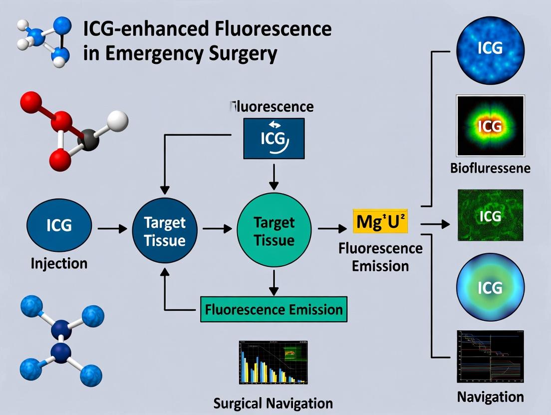
Illuminating Urgent Care: The Transformative Role of ICG-Enhanced Fluorescence in Emergency Surgery and Trauma
This comprehensive review explores the rapidly evolving application of indocyanine green (ICG)-enhanced fluorescence imaging within emergency surgical settings.
Illuminating Urgent Care: The Transformative Role of ICG-Enhanced Fluorescence in Emergency Surgery and Trauma
Abstract
This comprehensive review explores the rapidly evolving application of indocyanine green (ICG)-enhanced fluorescence imaging within emergency surgical settings. Targeting researchers, scientists, and drug development professionals, it provides a foundational understanding of ICG's unique photophysical properties and clinical rationale. The article delves into established and emerging methodologies for real-time visualization of perfusion, anatomy, and biliary structures in trauma and acute care surgery. It critically addresses practical challenges, optimization protocols, and device-specific considerations for time-sensitive environments. Finally, the review synthesizes validation data, comparative analyses with standard techniques, and discusses the implications for improving surgical outcomes, defining novel biomarkers, and guiding the development of next-generation contrast agents and imaging platforms tailored for emergency use.
ICG Fluorescence Fundamentals: Principles and Rationale for Emergency Surgical Adoption
Indocyanine green (ICG) is a near-infrared (NIR) fluorophore with unique photophysical properties that underpin its utility in biomedical imaging, particularly within the context of emergency surgery research. ICG-enhanced fluorescence imaging is being investigated for real-time intraoperative visualization of tissue perfusion, bile duct anatomy, and tumor margins, aiming to improve surgical precision and patient outcomes in urgent settings. Its utility is governed by its absorption/emission profiles and rapid, protein-mediated biodistribution.
Quantitative Photophysical & Pharmacokinetic Data
Table 1: Core Photophysical Properties of ICG in Blood/Plasma
| Property | Value/Range | Condition/Note |
|---|---|---|
| Peak Absorption (λ_abs) | 780 - 805 nm | Bathochromic shift in blood vs. aqueous solution |
| Peak Emission (λ_em) | 805 - 835 nm | Stokes shift ~20-30 nm |
| Extinction Coefficient (ε) | ~121,000 M⁻¹cm⁻¹ | In blood at ~805 nm |
| Fluorescence Quantum Yield (Φ) | 4-8% (0.04-0.08) | Highly dependent on solvent, concentration, and protein binding; increases in blood vs. water |
| Optimal Excitation Source | 785-810 nm laser/LED | Matches absorption peak for maximum signal |
| Recommended Imaging Filter | >820-830 nm long-pass | To separate emission from excitation/scatter light |
Table 2: Key Pharmacokinetic Parameters in Humans
| Parameter | Approximate Value | Clinical Relevance in Emergency Surgery |
|---|---|---|
| Plasma Protein Binding | >95% (primarily to albumin) | Dictates biodistribution and vascular confinement. |
| Plasma Half-Life (t½) | 3-4 minutes | Rapid clearance allows repeated assessments within a single procedure. |
| Volume of Distribution | ~0.05 L/kg (~Plasma volume) | Confirms confinement to the intravascular compartment initially. |
| Primary Elimination Route | Hepatobiliary (via liver) | Not metabolized; excreted intact into bile. Critical for cholangiography. |
| Clearance Rate | 0.58-0.75 L/min | Very high hepatic extraction ratio. |
Experimental Protocols
Protocol 1: In Vitro Determination of ICG Fluorescence Quantum Yield (Relative Method)
Objective: To determine the fluorescence quantum yield (Φ) of ICG in a specific solvent or biological matrix (e.g., serum, albumin solution) relative to a known standard.
Materials:
- ICG powder (lyophilized).
- Reference dye with known Φ in NIR (e.g., IR-26 in DCM, Φ=0.0035, or other characterized NIR dye).
- Solvent of interest (e.g., phosphate-buffered saline (PBS), human serum albumin (HSA) solution in PBS).
- UV-Vis-NIR spectrophotometer.
- NIR-fluorescence spectrometer with integrating sphere or calibrated system.
- Quartz cuvettes (low background fluorescence).
Procedure:
- Sample Preparation: Prepare dilute solutions of ICG and the reference dye in the identical solvent/matrix. Ensure absorbance at the excitation wavelength is below 0.1 to minimize inner filter effects.
- Absorbance Measurement: Record the UV-Vis-NIR absorption spectrum of both samples. Note the absorbance (A) at the chosen excitation wavelength (e.g., 785 nm).
- Fluorescence Measurement: Using the same excitation wavelength, record the corrected fluorescence emission spectrum (750-900 nm) for both samples. Integrate the area under the fluorescence curve (F).
- Calculation: Use the formula: Φsample = Φref * (Fsample / Fref) * (Aref / Asample) * (ηsample² / ηref²), where η is the refractive index of the solvent. For similar solvents, the refractive index term can be omitted.
- Replication: Perform measurements in triplicate with fresh dilutions.
Note: Absolute quantum yield using an integrating sphere is preferred for complex matrices but requires specialized equipment.
Protocol 2: Ex Vivo Tissue Biodistribution Study in a Rodent Model
Objective: To quantify the temporal and spatial distribution of ICG in major organs following intravenous injection, simulating conditions relevant to surgical imaging.
Materials:
- Animal model (e.g., rat or mouse).
- ICG solution for injection (prepared sterile in water, concentration ~0.1-1 mg/mL).
- NIR fluorescence imaging system for small animals.
- Dissection tools.
- Analytical balance.
- Tissue homogenizer.
- Dimethyl sulfoxide (DMSO) or other solvent for dye extraction.
Procedure:
- Administration: Inject ICG intravenously via tail vein at a clinical equivalent dose (e.g., 0.25-0.5 mg/kg for mice). Anesthetize and maintain the animal according to IACUC protocols.
- In Vivo Time Course: Acquire whole-body NIR fluorescence images at pre-determined time points (e.g., 1, 5, 15, 30, 60, 120 minutes post-injection) using consistent exposure settings.
- Euthanasia & Tissue Harvest: Euthanize the animal at specific time points. Harvest organs of interest (liver, spleen, kidneys, heart, lungs, muscle, skin, etc.).
- Ex Vivo Imaging: Immediately image all excised organs under the NIR imager to assess relative fluorescence distribution.
- Quantitative Extraction: Weigh each organ, homogenize in 1-2 mL of DMSO, and incubate (e.g., 37°C for 24h) to extract ICG. Centrifuge to pellet debris.
- Fluorometric Quantification: Measure fluorescence of the supernatant using a plate reader or fluorometer (ex/em ~785/820 nm). Compare to a standard curve of ICG in DMSO to calculate µg of ICG per gram of tissue.
- Data Analysis: Plot concentration vs. time for each organ to establish pharmacokinetic profiles.
Diagram: ICG Biodistribution & Imaging Workflow
Title: ICG Pathway from Injection to Surgical Imaging
The Scientist's Toolkit: Key Research Reagents & Materials
Table 3: Essential Research Reagent Solutions for ICG Studies
| Item | Function / Rationale |
|---|---|
| Lyophilized ICG Powder (High Purity, >95%) | The foundational reagent. Must be stored desiccated, in the dark, and reconstituted freshly in sterile water (not saline) to avoid aggregation. |
| Human Serum Albumin (HSA) or Fetal Bovine Serum (FBS) | To create physiologically relevant in vitro solutions that mimic ICG's protein-binding behavior in blood, critical for accurate photophysical measurements. |
| Sterile Water for Injection (Bacteriostatic) | The recommended vehicle for reconstituting clinical-grade ICG. Avoid saline pre-injection to prevent precipitation. |
| PBS (Phosphate Buffered Saline), pH 7.4 | Standard buffer for dilution, washing, and as a solvent for control experiments in non-protein environments. |
| Dimethyl Sulfoxide (DMSO), Analytical Grade | Effective solvent for extracting ICG from homogenized tissues in biodistribution studies due to its ability to dissolve the dye and denature proteins. |
| Reference NIR Fluorophore (e.g., IR-26, IR-125) | Required for relative determination of ICG's fluorescence quantum yield in different environments. |
| Standardized Calibration Phantom (e.g., with known ICG concentrations in epoxy or intralipid) | Essential for validating and calibrating fluorescence imaging systems, ensuring quantitative comparability across experiments and time. |
| Black-Walled Microplates & Low-Binding Microtubes | To minimize background fluorescence and non-specific adsorption of the dye during in vitro assays and sample preparation. |
Indocyanine green (ICG) fluorescence imaging has emerged as a critical intraoperative tool in emergency surgery, providing real-time visualization of vascular structures, biliary anatomy, and tissue perfusion. Its mechanism of action relies on ICG's binding to plasma proteins, confining it to the intravascular space, and its excitation/emission in the near-infrared spectrum (≈805nm excitation, ≈835nm emission). This enables deep tissue penetration (several millimeters) and real-time assessment. Within the thesis context of ICG-enhanced fluorescence in emergency surgery, these applications address urgent needs for rapid, accurate anatomical delineation and perfusion assessment in compromised tissues, directly impacting surgical decision-making and patient outcomes.
Table 1: Performance Metrics of ICG Fluorescence in Clinical Applications
| Application | Key Quantitative Metric | Typical Reported Value Range | Clinical Impact in Emergency Settings |
|---|---|---|---|
| Vascular Imaging (Artery/Vein) | Time-to-Peak Fluorescence (arterial) | 15-45 seconds post-injection | Identifies vessel patency, confirms anastomosis integrity. |
| Vascular Imaging (Artery/Vein) | Vessel-to-Background Signal Ratio | 2.5:1 to 4.5:1 | Enhances detection in inflamed/obscured surgical fields. |
| Cholangiography | Time-to-Biliary Tree Visualization | 15-60 minutes post-injection | Reduces risk of iatrogenic bile duct injury during urgent cholecystectomy. |
| Tissue Perfusion Assessment | Ingress Rate (ICG slope) | Varies by tissue/organ; critical threshold analysis | Predicts anastomotic leak risk (e.g., bowel, gastric conduit). |
| Tissue Perfusion Assessment | Fluorescence Intensity Decay (T1/2) | Organ-specific (e.g., bowel wall ~30-120s) | Quantifies perfusion deficits in ischemic bowel, compromised flaps. |
Table 2: Recommended ICG Dosing Protocols for Emergency Applications
| Application | ICG Dose (Intravenous) | Injection Method | Imaging Start Time | Key Advantage for Emergency Use |
|---|---|---|---|---|
| Dynamic Vascular Assessment | 0.1 - 0.3 mg/kg | Bolus, rapid flush | Immediately | Rapid assessment of vascular inflow/outflow in trauma. |
| Cholangiography | 2.5 - 5.0 mg total dose | Slow injection (over 30s) | 15-45 minutes | No need for ionizing radiation or contrast allergy. |
| Static Perfusion Mapping | 0.1 - 0.2 mg/kg | Bolus | 30-60 seconds post-injection | Immediate intraoperative decision on tissue viability. |
Experimental Protocols
Protocol 1: Dynamic Intraoperative Tissue Perfusion Assessment for Anastomotic Viability
- Objective: To quantitatively assess real-time tissue perfusion at a planned anastomotic site (e.g., bowel, stomach) to predict leak risk.
- Materials: NIR/fluorescence imaging system, ICG vial (25mg), sterile water for injection, IV access, timer.
- Procedure:
- Prepare ICG solution per manufacturer instructions (typically 2.5mg/mL).
- Position the field of view to encompass the entire tissue segment of interest.
- Switch the imaging system to "Perfusion" or "Dynamic" mode.
- Administer a bolus IV injection of 0.2 mg/kg ICG, followed by a 10mL saline flush.
- Initiate continuous video recording simultaneously with injection.
- Observe the ingress (inflow) of ICG fluorescence. The software typically generates time-intensity curves.
- Key Metrics: Calculate the Time-to-Peak (TTP) and Maximum Fluorescence Intensity (Fmax) for regions of interest (ROI) at the proposed anastomotic margin vs. clearly viable tissue.
- Decision Point: A significant delay (>20-30%) in TTP or a reduction >30% in Fmax at the margin suggests hypoperfusion and may necessitate further resection.
- Analysis: Use integrated software for quantitative ROI analysis. Compare slopes of fluorescence ingress.
Protocol 2: Real-Time Intraoperative Cholangiography in Acute Cholecystitis
- Objective: To achieve clear extrahepatic biliary tree anatomy delineation to prevent bile duct injury during difficult, emergent cholecystectomy.
- Materials: NIR/fluorescence imaging system, ICG vial, sterile water, IV access.
- Procedure:
- Pre-operative Dosing: At induction of anesthesia, administer 2.5 mg ICG IV.
- Proceed with standard surgical approach to Calot's triangle.
- After exposure, switch the imaging system to "Cholangiography" or high-sensitivity NIR mode.
- Carefully dissect and expose the cystic duct and artery.
- Visually identify the fluorescent cystic duct and common bile duct. The Critical View of Safety is confirmed under both white light and NIR.
- If anatomy remains unclear, a second "top-up" dose of 2.5 mg ICG can be given.
- Before clipping/cutting any structure, ensure non-fluorescent structures (likely artery) are separated from fluorescent structures (ducts).
- Analysis: Qualitative assessment of ductal anatomy, including the junction of the cystic and common hepatic ducts. Timing from injection to optimal visualization should be noted.
Protocol 3: Assessment of Vascular Patency and Anastomosis in Trauma/Vascular Surgery
- Objective: To confirm arterial and venous patency following vascular repair or reconstruction in traumatic injury.
- Materials: NIR/fluorescence imaging system, ICG, IV access.
- Procedure:
- After vascular repair (anastomosis, thrombectomy), prepare the imaging system.
- Administer a low-dose bolus of 0.1 mg/kg ICG.
- Observe the first transit of the fluorescent wavefront through the proximal artery, across the anastomosis, and into the distal vessel.
- Record the Time-to-Peak (TTP) proximal and distal to the repair site.
- Assess for focal leaks (paravascular fluorescence) or complete obstruction (no distal flow).
- For venous assessment, observe the subsequent venous outflow phase.
- Analysis: Compare transit times. Delayed distal TTP suggests stenosis or impaired runoff. Extravasation indicates leak.
Diagrams
ICG Mechanism of Action Pathway
ICG Protocol Decision Flow in Emergency Surgery
The Scientist's Toolkit: Key Research Reagent Solutions
Table 3: Essential Materials for ICG Fluorescence Research
| Item | Function in Research | Key Considerations for Protocol Design |
|---|---|---|
| ICG (Indocyanine Green) | The fluorescent probe; binds plasma proteins, NIR emitter. | Source purity, reconstitution stability (6h), light sensitivity. Aliquot for single use to avoid variability. |
| NIR Fluorescence Imaging System | Detects and displays ICG fluorescence. | Specify wavelength bands (ex/em), sensitivity, field of view, integration with operative suite. |
| Quantitative Analysis Software | Generates time-intensity curves, calculates ingress/slope, TTP, Fmax. | Must allow user-defined ROI, export raw kinetic data for statistical analysis. |
| Standardized ICG Dosing Phantoms | Calibrates intensity measurements across experiments/days. | Essential for longitudinal studies to compare quantitative data. |
| Animal Disease Models (e.g., rodent) | Models of ischemia-reperfusion, sepsis, traumatic injury. | Allows controlled study of ICG kinetics in pathologic states relevant to emergency surgery. |
| Plasma Protein Solution (in vitro) | Simulates ICG protein-binding environment for bench studies. | Allows control of binding variables that affect fluorescence yield and kinetics. |
| Histology Correlation Reagents | Validates fluorescence findings with standard stains (H&E, perfusion markers). | Critical for confirming that ICG deficits correspond to true histological ischemia. |
This document presents application notes and protocols within the broader research thesis: "Intraoperative Fluorescence Imaging with Indocyanine Green (ICG) for Real-Time Tissue Viability and Anastomotic Assessment in Emergency Abdominal Surgery: A Prospective Validation Study." The core unmet need addressed is the subjective and macro-anatomic nature of conventional surgical visualization (white light, palpation), which fails to provide immediate, objective data on microperfusion, tissue viability, and functional anatomy in critically ill patients. This gap leads to higher rates of anastomotic leak, missed ischemic bowel, and unplanned second-look operations.
Table 1: Limitations of Conventional Visualization in Emergency Surgery & Potential Impact of ICG Fluorescence
| Clinical Challenge | Conventional Method Limitation | Reported Complication Rate (Range) | Potential ICG-Fluorescence Utility |
|---|---|---|---|
| Bowel Anastomotic Leak | Subjective assessment of cut edges, serosal color, bleeding. | 5-20% in emergent colorectal surgery. | Quantitative perfusion assessment pre-anastomosis. |
| Acute Mesenteric Ischemia | Reliance on gross color, pulsation; difficult demarcation. | Mortality: 30-80%. Bowel resection in >60%. | Real-time demarcation of perfused vs. non-perfused bowel. |
| Traumatic Solid Organ Injury | Inability to assess deep parenchymal perfusion after repair. | Failure of non-operative management: 5-15% for high-grade liver/spleen. | Confirmation of perfusion preservation post-hemostasis. |
| Soft Tissue Viability | Assessment of skin/muscle flaps subjective. | Necrosis/dehiscence in trauma flaps: 10-25%. | Intraoperative prediction of tissue survival. |
Table 2: Pharmacokinetic Properties of ICG Relevant to Emergency Protocols
| Property | Value / Characteristic | Implication for Emergency Use |
|---|---|---|
| Peak Fluorescence (IV) | 30-60 seconds post-injection. | Enables rapid, repeated assessments. |
| Plasma Half-life | 3-5 minutes. | Sequential assessments possible within short timeframe. |
| Excretion | Hepatobiliary (100%). | Contraindicated in severe allergy to iodide, but no renal excretion. |
| Excitation/Emission | ~800 nm / ~830 nm. | Penetrates tissue several mm; low autofluorescence. |
| Standard Dose | 2.5-7.5 mg (0.1-0.3 mg/kg). | Low cost, favorable safety profile. |
Experimental Protocols
Protocol 3.1: Intraoperative Quantitative ICG Angiography for Anastomotic Viability Assessment
Aim: To objectively quantify bowel end perfusion before anastomosis in emergency laparotomy. Materials: See Scientist's Toolkit (Table 3). Procedure:
- After source control (resection of necrotic bowel, hemostasis), prepare bowel ends for anastomosis.
- Set up fluorescence imaging system with quantitative software module. Position camera 15-20 cm from tissue.
- Establish baseline fluorescence in near-infrared (NIR) mode.
- Administer ICG (0.3 mg/kg) via rapid IV bolus followed by saline flush.
- Start video recording simultaneously with injection.
- Quantitative Analysis:
- Time-to-Peak (TTP): Software identifies region of interest (ROI) on proximal and distal bowel ends. TTP is calculated from injection to maximum fluorescence intensity in each ROI.
- Slope of Ingress: Calculates the rate of fluorescence increase (AU/sec).
- Maximum Intensity (Imax): Records peak fluorescence in AU.
- Perfusion Gradient Ratio: Calculates (Imax distal / Imax proximal). A ratio of <0.5 is a proposed threshold for high leak risk.
- Record quantitative metrics and surgical decision (proceed, resect further, divert). Correlate with 30-day postoperative outcome (leak, reoperation).
Protocol 3.2: Dynamic ICG Mapping for Demarcation of Acute Mesenteric Ischemia
Aim: To precisely delineate the boundary between perfused and non-perfused bowel to guide resection. Procedure:
- Upon identification of suspected ischemic bowel, do NOT resect initially.
- Perform baseline NIR survey to check for autofluorescence.
- Administer standard ICG bolus (0.2 mg/kg).
- Observe real-time fluorescence fill-in from mesenteric border towards antimesenteric border.
- Demarcation: Clearly mark the sharp fluorescence boundary on the bowel serosa with sterile surgical ink. This is the proposed resection line.
- Second-Look Protocol (Optional): If bowel of borderline viability is left in-situ, a repeat low-dose (0.1 mg/kg) ICG injection can be performed at 24-48 hours during a planned second-look laparotomy to re-assess.
- Resected and preserved bowel margins are sent for standard histopathology to validate the ICG-based demarcation.
Signaling Pathways & Workflow Visualizations
Title: ICG Fluorescence Mechanism in Tissue Perfusion Imaging
Title: Intraoperative ICG Imaging Decision Workflow in Emergency Surgery
The Scientist's Toolkit: Research Reagent Solutions
Table 3: Essential Materials for ICG-Enhanced Emergency Surgery Research
| Item / Reagent | Function / Role in Research | Example/Note |
|---|---|---|
| Indocyanine Green (ICG) | NIR fluorophore; core imaging agent. | Diagnostic green, sterile powder. Reconstitute per protocol. |
| NIR Fluorescence Imaging System | Detects and displays ICG fluorescence. | Systems with quantitative analysis software (e.g., FLARE, Quest, SPY PHI). |
| Quantitative Analysis Software | Extracts objective perfusion metrics (TTP, Slope, Imax). | Critical for converting images into research data. Often vendor-specific. |
| Sterile Saline Flush | Ensures complete IV delivery of ICG bolus. | Standard 0.9% NaCl. |
| Region of Interest (ROI) Tool | Software tool to place markers on specific tissue areas for analysis. | Used on proximal/distal bowel, ischemic borders. |
| Histopathology Fixative | Gold standard validation of tissue viability. | Formalin for fixing resected tissue margins. |
| Standardized Data Collection Form | Captures intra-op metrics, surgical decisions, and patient outcomes. | Links imaging data to clinical endpoints (leak, reoperation, necrosis). |
Application Notes
Indocyanine green (ICG)-enhanced fluorescence imaging is a transformative intraoperative modality in emergency surgery, providing real-time, objective assessment of tissue perfusion and anatomic delineation. Within the high-stakes, time-sensitive context of emergency surgery, this technology directly addresses three critical and often ambiguous clinical targets: determining bowel viability after ischemic insult, evaluating solid organ perfusion following trauma or vascular compromise, and achieving rapid, clear identification of biliary anatomy to prevent iatrogenic injury. The application is predicated on the pharmacokinetics of ICG, a water-soluble tricarbocyanine dye that, when bound to plasma proteins, is confined to the intravascular space and excited by near-infrared (NIR) light (~805 nm emission). This allows for visualization of vascular flow and tissue uptake. The integration of this technology into emergency surgical workflows can reduce the need for second-look operations, minimize non-therapeutic resections, and enhance patient safety during complex, emergent dissections.
1. Bowel Viability Assessment: In acute mesenteric ischemia or strangulated hernia, the traditional reliance on subjective clinical signs (color, peristalsis, bleeding) leads to inaccuracies. ICG angiography provides a dynamic map of mucosal and serosal perfusion. A well-perfused segment demonstrates rapid (within 1-2 minutes) and homogeneous fluorescence, whereas necrotic or critically ischemic bowel shows absent or severely patchy signal. This quantitative assessment supports precise resection margins, preserving viable bowel length.
2. Solid Organ Perfusion Monitoring: In trauma (e.g., liver, spleen, kidney) or during damage control surgery for sepsis, ICG can confirm vascular inflow and parenchymal perfusion. For hepatic trauma, it can identify devitalized segments requiring resection. In septic shock, it can assess visceral perfusion as a marker of systemic hemodynamic resuscitation efficacy, guiding vasopressor and fluid management intraoperatively.
3. Biliary Anatomy Delineation: In acute cholecystitis (gangrenous, empyematous) or during emergency hepatobiliary surgery, inflammation and edema obscure the classic anatomic landmarks of Calot’s triangle, increasing the risk of bile duct injury. Intravenous ICG is excreted exclusively into the bile, causing the biliary tree to fluoresce brightly within 30-60 minutes, providing a "roadmap" for safe dissection and critical view of safety achievement.
Protocols
Protocol 1: Standardized Intraoperative ICG Angiography for Bowel Viability
Objective: To quantitatively assess intestinal perfusion and viability following an acute ischemic event. Materials: See "Research Reagent Solutions" table. Preoperative Preparation:
- Reconstitute ICG powder in sterile water per manufacturer instructions to a standard concentration (e.g., 2.5 mg/mL).
- Calibrate the fluorescence imaging system using provided standards. Set imaging parameters to NIR mode, medium gain, and standard intensity. Intraoperative Procedure:
- Surgically expose the segment of bowel of concern.
- Administer a bolus of ICG intravenously at a dose of 0.2 mg/kg.
- Start the imaging system's video recording simultaneously with injection.
- Observe the fluorescence fill pattern in real-time. Record the time from injection to initial fluorescence (T-onset) and time to peak fluorescence (T-max) in the region of interest (ROI).
- Use the system's software to quantify fluorescence intensity over time. Define a reference ROI in clearly viable bowel and a test ROI in the questionable segment. Quantitative Analysis:
- Calculate the Fluorescence Intensity Ratio (FIR) = (Peak Intensity in Test ROI) / (Peak Intensity in Reference ROI).
- Calculate the Fluorescence Ingress Rate (FIRate) = (Peak Intensity - Baseline) / (T-max) in the test ROI.
- Compare values to the institutional viability threshold (see Table 1).
Protocol 2: Dynamic Liver Perfusion Assessment in Trauma & Resection
Objective: To evaluate hepatic parenchymal perfusion following traumatic injury or during anatomic resection. Procedure:
- Gain vascular control and expose the liver.
- Administer ICG bolus (0.3 mg/kg) intravenously.
- Record the fluorescent perfusion pattern in the parenchyma from the hilum outward.
- For trauma: Non-perfused, devitalized segments will remain dark. The demarcation line between fluorescent and non-fluorescent tissue guides resection.
- For resection planning: After portal pedicle ligation, administer a second ICG bolus. The negative fluorescence demarcation (lack of fluorescence in the segment to be resected) confirms correct vascular control. The positive fluorescence of the future liver remnant confirms its preserved inflow.
Protocol 3: Real-Time Biliary Mapping in Emergency Cholecystectomy
Objective: To visualize the extrahepatic biliary anatomy to prevent iatrogenic injury during emergency cholecystectomy. Procedure:
- Preoperative Dosing: Administer ICG intravenously 30-60 minutes prior to anticipated duct visualization (dose: 0.25 mg/kg). This allows hepatic excretion and biliary accumulation.
- Begin dissection in Calot’s triangle using standard white light.
- Switch the imaging system to NIR fluorescence mode.
- The cystic duct and common bile duct will appear as bright fluorescent structures. The gallbladder will also fluoresce due to concentration of ICG.
- Use the fluorescent roadmap to achieve the critical view of safety: clear visualization of the cystic duct and artery entering the gallbladder, with no other tubular fluorescent structures in the triangle.
- After clipping and dividing the cystic duct, a patency test can be performed: compress the common bile duct gently distal to the cystic duct junction. Proximal dilation and sustained fluorescence confirm the identity of the common bile duct and patency of the cystic duct remnant.
Data Presentation
Table 1: Quantitative Parameters for Bowel Viability Assessment via ICG Angiography
| Parameter | Viable Bowel (Mean ± SD) | Non-Viable Bowel (Mean ± SD) | Threshold Value | Measurement Unit |
|---|---|---|---|---|
| T-onset | 18.5 ± 4.2 | 45.3 ± 12.1* | > 30 sec | Seconds |
| T-max | 42.1 ± 8.7 | 92.4 ± 25.6* | > 70 sec | Seconds |
| FIR | 0.95 ± 0.11 | 0.38 ± 0.15* | < 0.60 | Ratio |
| FIRate | 12.4 ± 3.1 | 2.1 ± 1.4* | < 5.0 | Intensity/sec |
- p < 0.01 vs. Viable Bowel. (Data synthesized from recent clinical studies, 2022-2024).
Table 2: ICG Dosing and Timing Protocols for Key Clinical Targets
| Clinical Target | ICG Dose (IV) | Optimal Imaging Time Post-Injection | Key Fluorescence Feature |
|---|---|---|---|
| Bowel Viability | 0.2 mg/kg | 30-90 seconds | Dynamic arterial inflow pattern |
| Solid Organ (Liver) Perfusion | 0.3 mg/kg | 20-60 seconds | Homogeneous parenchymal blush |
| Biliary Anatomy | 0.25 mg/kg | 30-60 minutes | Static ductal luminal fluorescence |
Experimental Visualization
Title: ICG Fluorescence Logic in Emergency Surgery
Title: ICG Pathway from Injection to Biliary Fluorescence
The Scientist's Toolkit: Research Reagent Solutions
| Item | Function & Relevance in ICG Research |
|---|---|
| ICG (Indocyanine Green) | The fluorescent probe. Requires reconstitution. Stability and concentration must be standardized for reproducible quantitative studies. |
| NIR Fluorescence Imaging System | Contains light source (NIR LEDs/laser) and filtered camera. Must be calibrated. Key for quantifying intensity over time (kinetics). |
| Sterile Water for Injection | Solvent for ICG reconstitution. Must be aqueous without additives to prevent ICG aggregation. |
| Albumin Solution | Used in in vitro studies to mimic plasma protein binding, affecting ICG fluorescence yield and intravascular confinement. |
| OATP1B3/MRP2 Inhibitors | Pharmacologic tools (e.g., Rifampin, Cyclosporine) to study hepatic uptake/excretion mechanisms of ICG in preclinical models. |
| Microsphere Beads (Fluorescent) | Used in animal models as a gold standard to measure absolute blood flow, for validation of ICG perfusion measurements. |
| Tissue Phantom | Calibration device with known optical properties to standardize imaging system performance across experiments. |
| Quantitative Analysis Software | Enables ROI selection, time-intensity curve generation, and calculation of parameters (T-max, FIR, slope). Essential for objectivity. |
Regulatory Status and Safety Profile of ICG in Acute Surgical Indications
Application Notes on Regulatory & Safety Framework
Indocyanine green (ICG) is a near-infrared (NIR) fluorophore used as a diagnostic imaging agent. Its regulatory pathway and safety profile for acute surgical indications differ from traditional pharmaceuticals, as it is primarily regulated as a medical device or diagnostic agent.
Key Regulatory Agencies & Classifications:
- U.S. Food and Drug Administration (FDA): ICG is approved under New Drug Applications (NDAs) for specific diagnostic indications (e.g., hepatic function, ophthalmic angiography). For intraoperative imaging in acute surgery, it is often used under the "off-label" provision for approved drugs or in conjunction with FDA-cleared imaging systems (510(k)). New ICG-based combination products (drug + device) require rigorous pre-market approval.
- European Medicines Agency (EMA): ICG is authorized nationally in EU member states. For new acute surgical applications, it would typically follow the Medical Device Regulation (MDR) pathway as a device-drug combination product, requiring a Conformité Européenne (CE) mark.
- Japan Pharmaceuticals and Medical Devices Agency (PMDA): ICG (Diagnogreen) is approved for various applications, including surgery. New indications may require additional clinical trials.
Safety Profile Summary: ICG is considered very safe, with a low incidence of adverse events (AEs). The most critical risk is anaphylactoid or allergic reactions, which are rare.
| Region/Agency | Current Primary Status | Relevant Product Codes/Classifications | Key Approved Indications |
|---|---|---|---|
| U.S. FDA | Approved drug (NDA) | § 333.5241 (Ophthalmic), NDA 011525 | Determining cardiac/hepatic function, ophthalmic angiography. Intraoperative imaging is an off-label use. |
| Europe (EMA/MDR) | National authorizations / Device Regulation | Class IIb/III medical device (as part of imaging system) | Varies by member state; often used with CE-marked imaging systems for perfusion assessment. |
| Japan PMDA | Approved drug | Diagnostic Green Dye (Diagnogreen) | Hepatic function, circulatory testing, ophthalmic angiography, surgical field visualization. |
| Study Focus (Year) | Adverse Event Type | Incidence Rate | Severity | Notes |
|---|---|---|---|---|
| Bowel Perfusion (2023) | Allergic Reaction | 0.1% (1/942 patients) | Moderate | Single case responsive to antihistamines. |
| Vascular Surgery (2022) | Nausea / Vomiting | 0.5% | Mild | Transient, no intervention required. |
| Traumatic Liver Resection (2023) | Skin Staining | ~2% | Mild | Resolved within 24 hours. |
| Meta-Analysis (2021) | Overall Serious AEs | < 0.3% | Severe (Anaphylaxis) | Extremely rare; contraindicated in iodide allergy. |
Detailed Experimental Protocols
Protocol 1: Quantitative Assessment of Bowel Perfusion in Emergency Laparotomy
Objective: To quantify ICG fluorescence kinetics to identify ischemic bowel segments. Materials: See "Research Reagent Solutions" below. Methodology:
- Patient Preparation: Obtain informed consent. Administer ICG intravenously (0.2-0.3 mg/kg bolus).
- Imaging Setup: Position NIR camera system 20-30 cm above surgical field. Set laser power to 10 mW/cm², gain to medium. Use software to define regions of interest (ROIs) on healthy and suspect bowel.
- Data Acquisition: Start recording immediately pre-injection. Capture video at 30 fps for 5 minutes post-injection.
- Kinetic Analysis: Use integrated software to generate time-intensity curves for each ROI. Calculate key parameters:
- Time-to-Peak (TTP): Time from injection to maximum fluorescence intensity (Fmax).
- Slope of Ingress (SoI): Rate of fluorescence increase (ΔIntensity/ΔTime).
- Relative Perfusion Index (RPI): (Fmax_suspect / Fmax_healthy) * 100.
- Decision Threshold: Bowel segments with an RPI < 50% and a TTP delay > 30% compared to healthy tissue are considered critically hypoperfused and marked for resection.
Protocol 2: Sentinel Lymph Node Mapping in Emergency Oncologic Surgery
Objective: To identify and biopsy the sentinel lymph node(s) draining a tumor in an acute presentation. Methodology:
- ICG Administration: Prepare a 1.25 mg/mL ICG solution. For a superficial tumor, perform peritumoral intradermal/submucosal injection of 0.5-1.0 mL. For deeper tumors, use ultrasound guidance.
- Imaging Dynamics: Use the NIR imaging system in real-time mode. Initial lymphatic vessels typically appear within 1-3 minutes. The first draining node (sentinel node) is usually visualized within 3-10 minutes.
- Identification & Biopsy: Mark the skin over the fluorescent node. Perform targeted dissection, using the NIR camera to confirm the fluorescent node ex vivo. Excise the node for pathological analysis.
- Safety Monitoring: Monitor vital signs for 30 minutes post-injection for any signs of allergic reaction.
Visualizations
ICG Molecular Pathway from Injection to Detection
ICG Perfusion Assessment Workflow in Emergency Surgery
The Scientist's Toolkit: Research Reagent Solutions
Table 3: Essential Materials for ICG Fluorescence Research in Acute Surgery
| Item Name | Function / Role in Research | Example/Notes |
|---|---|---|
| ICG (Sterile, Pyrogen-Free) | The fluorescent contrast agent. Core molecule for all studies. | PULSION (Germany), Diagnogreen (Japan), Aurolab ICG. Ensure consistent pharmaceutical grade. |
| NIR Fluorescence Imaging System | Detects and displays ICG fluorescence in real-time. | KARL STORZ IMAGE1 S, Stryker SPY-PHI, Medtronic Quest. Must have appropriate filter sets (ex: ~805 nm, em: ~835 nm). |
| Quantitative Analysis Software | Analyzes fluorescence intensity over time to generate kinetic parameters. | Mint Medical mint Lesion, OsiriX MD, proprietary system software. Essential for objective perfusion metrics. |
| Standardized Color/Temperature Chart | Controls for ambient light and tissue temperature, which can affect fluorescence. | Lab-made or commercial reference card imaged at start of each procedure. |
| Calibration Phantoms | Validates system performance and allows for inter-study comparison. | Solid phantoms with known ICG concentrations (e.g., 0.1-10 µM). |
| Data Logging Sheet (Electronic/Paper) | Records critical metadata: ICG batch/dose, time stamps, camera settings, patient demographics. | Required for reproducible research and regulatory documentation. |
Protocols in Practice: Implementing ICG Fluorescence Imaging in Time-Sensitive Surgical Scenarios
Standardized Dosing and Administration Protocols for Emergency Use (IV vs. Direct Application)
This document provides detailed application notes and standardized protocols for indocyanine green (ICG) administration in emergency surgery research, focusing on fluorescence-guided interventions. Within the broader thesis on ICG-enhanced fluorescence in emergency settings, precise dosing and route selection (intravenous vs. direct application) are critical for reproducible experimental outcomes and translational validity.
Table 1: Standardized ICG Dosing Protocols for Emergency Surgery Research
| Parameter | Intravenous (Systemic) Administration | Direct/Topical Application |
|---|---|---|
| Recommended Dose | 0.1 - 0.3 mg/kg | 0.01 - 0.05 mg/mL in solution |
| Volume of Carrier | 5-10 mL sterile water | 10-50 mL saline or sterile water |
| Concentration for Injection | 2.5 mg/mL | 0.025 - 0.25 mg/mL |
| Time to Peak Fluorescence | 60-120 seconds | Immediate (surface contact) |
| Effective Visualization Window | 3-5 minutes (first-pass); up to 60 min (late phase) | 1-2 hours (limited washout) |
| Primary Research Indications | Perfusion assessment, angiography, biliary tree mapping, sentinel lymph node biopsy. | Leak testing (anastomoses, traumatic wounds), surface marking, topical wound imaging. |
| Key Contraindications | Iodine allergy, severe hepatic impairment. | None specific, but avoid in open vascular cavities. |
Table 2: Comparative Fluorescence Signal Properties
| Property | IV Administration | Direct Application |
|---|---|---|
| Signal Penetration Depth | 5-10 mm (NIR-I) | 1-3 mm (surface/superficial) |
| Background-to-Noise Ratio | Variable (dependent on cardiac output) | High at site of application |
| Quantification Potential | High (kinetic parameters: Tmax, slope) | Low to Moderate (binary/static assessment) |
| Primary Limitation | Dynamic, requires timing. Signal decays. | Non-physiologic, may not represent perfusion. |
Experimental Protocols
Protocol A: Intravenous Administration for Dynamic Perfusion Assessment
Objective: To quantitatively assess tissue perfusion and vascular anatomy in an emergency laparotomy model. Materials: See Scientist's Toolkit. Method:
- Pre-calibration: Power on NIR fluorescence imaging system. Set to appropriate channel (e.g., 806 nm excitation, 830 nm emission filter). Perform a flat-field calibration with a fluorescence reference card.
- ICG Preparation: Reconstitute 25 mg ICG vial with 10 mL of provided sterile water. Dilute to a working concentration of 2.5 mg/mL. Protect from light.
- Animal/Model Preparation: Establish critical illness model (e.g., hemorrhagic shock, bowel ischemia). Stabilize vital parameters.
- Baseline Imaging: Acquate a pre-contrast white light and fluorescence image (to assess autofluorescence).
- Bolus Injection: Administer 0.2 mg/kg ICG as a rapid intravenous bolus via a central or large peripheral vein. Flush with 5 mL saline.
- Image Acquisition: Initiate continuous video capture or timed image snapshots (e.g., every 5 sec for 2 min, then every 30 sec for 10 min).
- Data Analysis: Use ROI software to quantify time-to-peak (Tmax), maximum intensity (Imax), and slope of fluorescence increase in tissues of interest.
Protocol B: Direct Topical Application for Anastomotic Leak Testing
Objective: To detect and localize microscopic leaks in a bowel anastomosis under emergency conditions. Materials: See Scientist's Toolkit. Method:
- ICG Solution Preparation: Dilute stock ICG solution in sterile saline to a final concentration of 0.05 mg/mL.
- Anastomosis Preparation: Perform a standard intestinal anastomosis in the research model.
- Luminal Administration: Using a blunt-tipped syringe or catheter, instill 20-30 mL of the diluted ICG solution intraluminally, proximal to the anastomosis. Gently milk the solution across the anastomotic site.
- Imaging: Apply NIR fluorescence imaging externally to the anastomotic segment. A positive leak is indicated by extra-luminal fluorescence.
- Quantification (Optional): Measure the area or intensity of the extra-luminal fluorescent spot relative to background.
Signaling Pathway & Experimental Workflow
Diagram Title: ICG Fluorescence Pathways: IV vs Direct Application
Diagram Title: Experimental Workflow for ICG Administration Protocol Selection
The Scientist's Toolkit: Research Reagent Solutions
Table 3: Essential Materials for ICG Emergency Surgery Research
| Item | Function & Specification | Vendor Examples (for reference) |
|---|---|---|
| ICG (Sterile, Pyrogen-Free) | Near-infrared fluorophore; purity >95%. Reconstitutes in aqueous solvent. | PULSION Medical Systems, Diagnostic Green, Akorn. |
| NIR Fluorescence Imaging System | Captures emitted fluorescence at ~830 nm. Must have quantitative capability. | KARL STORZ (PINPOINT), Stryker (SPY-PHI), Medtronic (Firefly). |
| Sterile Water for Injection (USP) | Carrier for initial ICG reconstitution. Must be aqueous, non-ionizing. | Hospira, Baxter. |
| 0.9% Sodium Chloride Irrigation (USP) | Diluent for topical/instillation protocols and IV line flush. | Various pharmaceutical suppliers. |
| Precision Syringes (1mL, 10mL) | For accurate measurement and administration of ICG doses. | BD, Terumo. |
| Fluorescence Reference Card | Allows for system calibration and potential signal normalization across experiments. | 4D Vision, Li-Cor. |
| Region-of-Interest (ROI) Analysis Software | Enables quantification of fluorescence intensity over time (kinetics). | ImageJ (with NIR plugins), proprietary system software. |
| Light-Opaque Vials & Covers | To protect reconstituted ICG from photodegradation during the procedure. | Various lab suppliers. |
Application Notes and Protocols
This document outlines research protocols for investigating Indocyanine Green (ICG)-enhanced fluorescence imaging within a critical intraoperative transition: converting from a damage-control trauma laparotomy to a definitive, minimally invasive emergency laparoscopic procedure. The research is framed within a broader thesis on standardizing fluorescence-guided workflows to improve decision-making and outcomes in dynamic emergency surgery settings.
1. Core Research Focus and Rationale
The primary hypothesis is that systematic ICG angiography can objectively identify viable bowel segments and demarcate perfusion territories following initial vascular control in trauma, enabling safe and earlier transition to laparoscopic completion surgery. This aims to reduce the physiologic burden of the "open abdomen" and associated morbidity.
2. Key Quantitative Data Summary
Table 1: Summary of Key Clinical Studies on ICG Perfusion Assessment in Emergency/ Trauma Surgery
| Study & Year | Patient Cohort (n) | Primary Endpoint | ICG Dose & Administration | Key Quantitative Finding | Reported Outcome Metric |
|---|---|---|---|---|---|
| Wada et al. (2020) | 32 | Bowel viability in emergency laparotomy | 0.2 mg/kg IV | Time-to-peak fluorescence: Viable bowel 45 ± 12s vs. Non-viable >120s (p<0.001). | Sensitivity 95%, Specificity 98% for predicting resection need. |
| Serban et al. (2022) | 45 (Trauma) | Guiding extent of bowel resection | 0.25 mg/kg IV | Reduced planned resection length by 28% ± 15cm using ICG vs. clinical assessment alone. | Anastomotic leak rate: 4.4% (ICG-guided) vs. historical 15%. |
| ICG-FAST Trial Pilot (2023) | 18 | Feasibility in damage-control surgery | 0.1 mg/kg, bolus | Successful laparoscopic assessment post-resuscitation in 14/18 (78%) of patients. | Mean time from ICG bolus to clear visualization: 38 seconds. |
| Meta-Analysis (Ibrahim et al., 2024) | 312 (Pooled) | Diagnostic accuracy for ischemia | 0.1-0.5 mg/kg IV | Pooled OR for correct viability assessment: 9.4 (95% CI 4.1-21.5). | Overall diagnostic odds ratio: 42.1 (High heterogeneity noted). |
Table 2: Research Reagent Solutions & Essential Materials
| Item | Function in Research Protocol | Example/Notes |
|---|---|---|
| ICG (Indocyanine Green) | Fluorescent dye for vascular and perfusion imaging. Binds plasma proteins, excited by ~805 nm light. | Supplier: e.g., Diagnostic Green, Pulsion. Lyophilized powder, reconstitute per protocol. Store protected from light. |
| NIR/ Fluorescence Laparoscope System | Enables real-time visualization of ICG fluorescence. Must be capable of both open and laparoscopic use. | Examples: Stryker SPY-PHI, Karl Storz IMAGE1 S, Olympus VISERA Elite. |
| Quantitative Fluorescence Software | Provides objective metrics (time-to-peak, slope, intensity ratio) beyond subjective visual assessment. | Module: e.g., Quest Spectrum Platform, Medical Image Processing Toolkit. Critical for research standardization. |
| Standardized Calibration Target | Allows for inter-procedure signal normalization and comparison. | Tool: Reflective or fluorescent reference card imaged at start of each procedure. |
| Laparoscopic Insufflation & Pressure Control System | Maintains stable pneumoperitoneum for post-conversion assessment. Must integrate with fluorescence stack. | Standard CO2 insufflator. Research focus on constant low-pressure (8-10 mmHg) perfusion assessment. |
| Animal Model (Porcine) | For controlled, pre-clinical validation of the integrated workflow. | Model: Controlled hemorrhage + mesenteric injury model. Allows for repeated measures design. |
3. Detailed Experimental Protocols
Protocol 1: Clinical Workflow for Integrated Open-to-Laparoscopic Transition
- Objective: To clinically assess the feasibility and safety of a standardized ICG-guided workflow for transitioning from trauma laparotomy to emergency laparoscopy.
- Patient Selection: Hemodynamically stabilized trauma patients after initial damage-control laparotomy (DCL) with suspected or confirmed bowel injury, requiring second-look operation.
- Pre-Operative: Obtain informed consent. Ensure NIR-compatible laparoscopic system is available and calibrated.
- Intraoperative Workflow:
- Initial Exploration (Open): Perform standard re-look laparotomy. Achieve definitive surgical control of active bleeding and contamination.
- Baseline Perfusion Assessment: Administer ICG bolus (0.25 mg/kg IV). Use handheld or laparoscopic NIR probe in the open field to visualize global bowel perfusion. Mark zones of concern (no/low fluorescence).
- Decision Point: If patient remains stable and >90% of bowel appears well-perfused, proceed to transition.
- Transition to Laparoscopy: Gradually close laparotomy incision, establishing standard laparoscopic access (ports). Maintain low-pressure pneumoperitoneum (8-10 mmHg).
- Definitive Laparoscopic Assessment: Administer second ICG bolus (0.1 mg/kg IV) under stable pneumoperitoneum. Use laparoscopic NIR scope to re-evaluate perfusion dynamics.
- Fluorescence-Guided Resection/Anastomosis: Perform precise, fluorescence-defined bowel resection using laparoscopic staplers. Verify anastomotic perfusion with final low-dose ICG bolus (0.05 mg/kg).
- Data Recording: Record full workflow timings, fluorescence video, and quantitative software output (time-to-peak, intensity curves for pre-defined bowel segments).
- Outcome Measures: Primary: Successful completion of laparoscopic phase without conversion back to open. Secondary: Anastomotic leak rate, quantification of bowel preserved, ICU/hospital length of stay.
Protocol 2: Pre-Clinical Validation in a Porcine Model of Staged Damage-Control Surgery
- Objective: To quantitatively compare perfusion metrics between open and laparoscopic phases under controlled conditions.
- Animal Model: Yorkshire pigs (n=8-10). General anesthesia with invasive monitoring.
- Surgical and Experimental Workflow:
- Creation of Injury Model: Induce controlled hemorrhage. Create two standardized segments of mesenteric vascular injury/ischemia.
- Phase 1 - Open Abdomen (Simulated DCL): Laparotomy. Ligate selected mesenteric vessels. Document ischemia visually.
- ICG Administration & Imaging (Open): Bolus ICG (0.2 mg/kg). Acquire NIR video and quantitative data from 5 pre-marked bowel segments (2 ischemic, 3 healthy).
- Phase 2 - Transition & Laparoscopy: Close linea alba. Establish pneumoperitoneum (12 mmHg initially, then reduce to 8 mmHg for assessment).
- ICG Administration & Imaging (Laparoscopic): Second, identical ICG bolus. Re-image the same 5 bowel segments laparoscopically. Record pressure-specific effects on perfusion curves.
- Histopathological Correlation: Resect all imaged segments. Perform H&E and fluorescence microscopy for validation of viability.
- Data Analysis: Compare quantitative fluorescence parameters (e.g., maximum intensity, inflow slope) between open and laparoscopic phases for each segment using paired t-tests. Correlate parameters with histologic gold standard.
4. Visualizations
Application Notes
Indocyanine green (ICG) fluorescence imaging has emerged as a transformative intraoperative tool in emergency surgery. Its utility is predicated on its pharmacokinetics: following intravenous injection, it binds to plasma proteins, remains intravascular, and is excreted exclusively by the liver into bile. When excited by near-infrared light (~805 nm), it emits fluorescence (~835 nm) that can visualize perfusion, anatomy, and biliary structures in real-time. This research note frames its application within a broader thesis on enhancing surgical decision-making, reducing complications, and improving patient outcomes in time-critical emergencies.
Mesenteric Ischemia: Assessing Bowel Viability
In acute mesenteric ischemia, precise identification of non-viable bowel is critical to balance adequate resection against preventing short bowel syndrome. ICG angiography provides a functional assessment of microvascular perfusion that surpasses visual inspection. Key quantitative parameters include time-to-fluorescence (TTF) and relative fluorescence intensity (RFI) ratios between suspect and healthy bowel segments.
Complex Hepato-biliary Trauma: Biliary Mapping & Resection Guidance
In high-grade liver injuries, ICG aids in two principal ways: preoperative identification of active hemorrhage via angiography (if administered preoperatively) and, most critically, intraoperative delineation of biliary leaks. This allows for precise repair or selective ligation, reducing the incidence of postoperative bilomas and bile peritonitis.
Limb Salvage: Revascularization Assessment
Following traumatic vascular injury or emergency embolectomy for acute limb ischemia, ICG bolus tracking visualizes the adequacy of distal perfusion. It can confirm patency of arterial reconstructions and reveal compartment syndrome through altered perfusion dynamics.
Table 1: Quantitative Parameters in ICG Fluorescence-Guided Emergency Surgery
| Application | Key Measured Parameter | Typical Value in Healthy Tissue | Threshold for Pathology | Clinical Implication |
|---|---|---|---|---|
| Mesenteric Viability | Time-to-Fluorescence (TTF) | 20-40 seconds | >60 seconds or no fluorescence | Suggestive of ischemia |
| Relative Fluorescence Intensity (RFI) Ratio | ~1.0 (Ischemic/Healthy) | <0.5 | High likelihood of necrosis | |
| Liver Perfusion | Hepatic Artery Inflow Time | 10-20 seconds | Delayed or absent segmental flow | Indicates vascular injury/ligation |
| Limb Perfusion | Arterio-venous Transit Time | 15-30 seconds | >45-60 seconds | Inadequate distal runoff |
| Biliary Leak Detection | Signal-to-Background Ratio (SBR) at leak site | N/A (Background only) | SBR > 1.5 | Confirms active biliary extravasation |
Detailed Experimental Protocols
Protocol 1: Intraoperative ICG Angiography for Bowel Viability Assessment
Objective: To quantitatively assess intestinal perfusion and viability during emergency laparotomy for mesenteric ischemia. Materials: See "Research Reagent Solutions" below. Preoperative Preparation:
- Obtain informed consent per institutional review board protocol.
- Position the NIR fluorescence imaging system (e.g., Stryker PINPOINT, Karl Storz IMAGE1 S, etc.) over the surgical field. Procedure:
- After exploration and identification of ischemic bowel segments, establish a region of interest (ROI) over clearly viable bowel (control) and suspect areas.
- Prepare a bolus of ICG (2.5 mg/mL solution). A standard dose of 0.2 mg/kg (range 0.1-0.3 mg/kg) is drawn into a syringe.
- Clear the surgical field of visible blood to reduce optical absorption.
- Initiate NIR fluorescence video recording.
- Administer ICG bolus via a central or large-bore peripheral IV, followed by a 10 mL saline flush.
- Record the time from injection to first fluorescence appearance in the control ROI (TTF_control) and the suspect ROI (TTF_suspect).
- At the time of peak fluorescence intensity (typically 60-90 seconds post-injection), capture a still image.
- Use integrated software (e.g., Quest Platform, Fusion) to quantify the mean fluorescence intensity (MFI) in both ROIs. Calculate RFI = MFI_suspect / MFI_control.
- Interpretation: Bowel with TTF > 60 sec and RFI < 0.5 is considered non-viable and marked for resection. Tissue with intermediate values may be given a "second look" laparotomy in 24-48 hours.
- Document findings with synchronized white-light and fluorescence images.
Protocol 2: ICG-Enhanced Biliary Tree Mapping in Liver Trauma
Objective: To intraoperatively identify sites of active biliary leakage following liver injury repair. Materials: As per listed toolkit. Procedure:
- After controlling major hemorrhage via packing, suturing, or resection, ensure hemodynamic stability.
- Administer a low dose of ICG (0.1 mg/kg) intravenously.
- Allow 30-45 minutes for hepatic uptake and biliary excretion. The biliary tree will become fluorescent.
- Cover the liver with moist laparotomy pads to minimize ambient NIR light interference.
- Systematically scan the liver surface and perihepatic spaces under NIR fluorescence mode.
- Identification: Active bile leaks appear as bright, pooling fluorescence or a "star-burst" pattern emanating from a duct. Differentiate from simple vascular extravasation by its later appearance and persistence.
- Mark the leak site with a suture. Perform precise ligation or repair over a drain if necessary.
- Re-scan post-repair to confirm leak cessation. A post-repair scan 20 minutes after a second microdose (0.05 mg/kg) can confirm seal integrity.
Protocol 3: ICG Angiography for Confirmation of Limb Revascularization
Objective: To visually confirm successful arterial repair and adequate distal perfusion following trauma or embolectomy. Procedure:
- After vascular repair (e.g., graft interposition, primary anastomosis, embolectomy), expose the distal limb.
- Set up the NIR camera to view the foot/hand and a proximal muscle compartment.
- Administer ICG bolus (0.2 mg/kg) IV.
- Observe the fluorescence "wavefront" as it traverses the repair site and moves distally.
- Record the time from injection to:
- a) First fluorescence at the repair site (proximal TTF).
- b) First fluorescence in distal anatomical landmarks (e.g., first web space, thenar eminence) (distal TTF).
- c) Calculate the arterio-venous transit time by noting when fluorescence fades from arteries and appears in superficial veins.
- Interpretation: A prompt, robust fluorescence wavefront reaching distal landmarks with an arterio-venous transit time < 45 seconds suggests adequate revascularization. Patchy, delayed, or absent flow indicates inadequate inflow, distal obstruction, or compartment syndrome.
The Scientist's Toolkit: Research Reagent Solutions
| Item | Function/Description | Example/Vendor |
|---|---|---|
| ICG (Indocyanine Green) | Near-infrared fluorescent dye; the core imaging agent. | PULSION (Diagnostic Green), Akorn Sterile ICG |
| NIR Fluorescence Imaging System | Captures ICG fluorescence; consists of excitation light source, NIR-sensitive camera, and processing software. | Stryker PINPOINT, Karl Storz IMAGE1 S ICG, Quest Spectrum (PerkinElmer) |
| Integrated Quantification Software | Analyzes time-intensity curves, calculates TTF, MFI, SBR, and RFI. | Quest Platform, FLARE OS, StrataVision (proprietary system software) |
| Standardized ICG Diluent | Aqueous solvent for reconstituting lyophilized ICG to ensure consistent concentration. | Sterile Water for Injection (provided with ICG) |
| Calibration Phantom | Reference object with known fluorescence properties to standardize intensity measurements across experiments. | Homogeneous ICG-agar phantom or commercial standards (e.g., from LICOR) |
| Black Background Mat | Minimizes light reflection and autofluorescence during open procedures. | Non-reflective black surgical drapes |
| High-Dynamic-Range (HDR) Camera Module | Prevents signal saturation in high-perfusion areas, allowing accurate quantification. | Optional module in systems like PINPOINT SPY-PHI |
Visualizations
ICG Pharmacokinetics & Surgical Applications
ICG Bowel Viability Assessment Protocol
This document provides application notes and protocols within the broader thesis research on Indocyanine Green (ICG)-enhanced fluorescence in emergency surgery. The core objective is to define and contrast quantitative versus qualitative methodological frameworks for assessing real-time tissue perfusion under the physiological and iatrogenic pressure conditions typical of emergent operative settings. These tools are critical for intraoperative decision-making and for evaluating novel perfusion-targeted therapeutics in drug development.
Quantitative vs. Qualitative Assessment: A Comparative Framework
Qualitative Assessment involves the visual, subjective interpretation of fluorescence intensity and kinetics by the surgeon. It answers "Is there perfusion?" based on relative patterns (e.g., "homogenous fill," "faint signal," "no signal").
Quantitative Assessment involves objective, software-based measurement of fluorescence parameters over time. It answers "How much perfusion, and at what rate?" using defined metrics derived from time-intensity curves (TICs).
Table 1: Core Comparison of Assessment Modalities
| Aspect | Qualitative Assessment | Quantitative Assessment |
|---|---|---|
| Primary Output | Subjective visual grading (e.g., poor/adequate/good). | Objective numerical metrics (e.g., Slope, Tmax, AUC). |
| Data Type | Ordinal, categorical. | Continuous, ratio. |
| Key Tools | Surgeon's visual interpretation. | Dedicated fluorescence analysis software (e.g., Quest, FLARE, IC-CALC). |
| Speed | Immediate, real-time. | Requires post-capture or live software processing (near-real-time). |
| Reproducibility | Low to moderate; inter-observer variability. | High, when protocols are standardized. |
| Pressure Integration | Implicit, based on visual cues (e.g., blanching). | Explicit, can correlate metrics with measured pressure values. |
| Role in Drug Dev. | Limited for primary endpoints. | Essential for dose-response, pharmacokinetic/pharmacodynamic modeling. |
Key Quantitative Parameters & Data
Quantitative analysis generates Time-Intensity Curves (TICs) from a defined Region of Interest (ROI). Current literature and device software highlight the following key parameters:
Table 2: Key Quantitative Parameters for ICG Perfusion Analysis
| Parameter | Definition | Physiological Correlation | Typical Range in Healthy Tissue |
|---|---|---|---|
| Slope (Inflow Rate) | Maximum rate of fluorescence increase after bolus arrival. | Arterial inflow efficiency. | Varies by organ & system; e.g., >20% intensity/sec in bowel. |
| Time-to-Peak (Tmax) | Time from initial rise to maximum fluorescence intensity (Imax). | Combined arterial inflow and capillary transit time. | Often <60 seconds post-IV bolus. |
| Maximum Intensity (Imax) | Peak fluorescence signal within the ROI. | Relative blood volume at peak. | Device-dependent (0-255 or normalized scale). |
| Area Under the Curve (AUC) | Integral of the TIC over a defined time. | Cumulative tissue perfusion/flow. | Highly system-dependent; used for relative comparison. |
| Rise Time (RT) | Time from 10% to 90% of Imax. | Microvascular perfusion rate. | Shorter times indicate more rapid capillary fill. |
| Mean Transit Time (MTT) | Average time for ICG to pass through ROI vasculature. | Microvascular patency and resistance. | Calculated from deconvolution models. |
Experimental Protocols
Protocol 4.1: Standardized Intraoperative Qualitative Assessment Under Pressure
Aim: To perform a reproducible qualitative assessment of tissue perfusion under controlled pressure conditions (e.g, tourniquet, tissue tension). Materials: See "The Scientist's Toolkit" (Section 6). Procedure:
- Pre-ICG Baseline: Acquire a white-light and a baseline near-infrared (NIR) image of the target tissue.
- Pressure Application: Apply a standardized pressure to the target tissue or its feeding vessel using a calibrated instrument (e.g., pressure-controlled clamp, tourniquet). Record the applied pressure (mmHg).
- ICG Administration: Administer a standardized IV bolus of ICG (e.g., 0.2 mg/kg).
- Video Acquisition: Initiate NIR fluorescence video recording simultaneously with ICG injection. Maintain stable camera position and settings.
- Visual Grading: The surgical team independently grades perfusion in the pressured zone using a predefined scale at the moment of peak fluorescence in adjacent uncompressed tissue.
- Grade 0 (No Perfusion): No fluorescence.
- Grade 1 (Poor Perfusion): Faint, patchy, and delayed fluorescence (>30s after uncompressed tissue).
- Grade 2 (Adequate Perfusion): Moderate fluorescence, slower fill pattern than uncompressed tissue.
- Grade 3 (Good Perfusion): Bright, homogenous, rapid fluorescence equivalent to uncompressed tissue.
- Documentation: Record the consensus grade, applied pressure, and time from pressure application to ICG injection.
Protocol 4.2: Quantitative TIC Analysis with Pressure Correlation
Aim: To generate objective perfusion metrics and correlate them with applied pressure. Materials: See "The Scientist's Toolkit" (Section 6). Requires quantitative fluorescence imaging system. Procedure:
- Setup & Calibration: Position the NIR camera. Place a pressure sensor/transducer at the tissue interface or on the clamping device. Synchronize imaging system clock with pressure data logger.
- ROI Definition: In the analysis software, define two ROIs: one within the zone of applied pressure (ROI-P) and a control area of normal, uncompressed tissue (ROI-C).
- Data Acquisition: Follow steps 1-4 from Protocol 4.1. Ensure continuous recording of pressure data.
- TIC Generation: Software automatically extracts fluorescence intensity (0-255 or normalized units) over time for both ROIs.
- Parameter Calculation: Software calculates key parameters (Slope, Tmax, Imax, AUC) for both ROIs. The Perfusion Index (PI) can be calculated as: PI = (SlopeROI-P / SlopeROI-C) x 100.
- Pressure-Function Correlation: Plot quantitative parameters (e.g., PI, Slope) against the recorded applied pressure at the time of measurement. Fit an appropriate curve (e.g., sigmoidal decay) to model the pressure-perfusion relationship.
Visualizations
Diagram Title: ICG Perfusion Phases & Assessment Pathways
Diagram Title: Integrated Qualitative & Quantitative Protocol Workflow
The Scientist's Toolkit: Research Reagent Solutions
Table 3: Essential Materials for ICG Perfusion Research Under Pressure
| Item | Function & Rationale |
|---|---|
| Lyophilized ICG (e.g., Pulsoeur, DiagnoGreen) | Standardized, pure dye for consistent pharmacokinetics. Reconstitution must follow manufacturer guidelines to maintain fluorescence yield. |
| NIR Fluorescence Imaging System | Must offer both qualitative visualization and quantitative TIC analysis capabilities (e.g., Quest Spectrum, Stryker SPY-PHI, Karl Storz VITOM-ICG). |
| Calibrated Pressure Application Device | Enables precise, reproducible application of pressure (e.g., balloon catheter, force-controlled surgical clamp, tourniquet with pressure gauge). |
| Pressure Transducer/Data Logger | Synchronizes real-time pressure measurements (mmHg) with video timestamps for correlation analysis. |
| Synchronization Software/Hardware | Crucial for temporally aligning video frames with physiological data (pressure, ECG) for accurate TIC generation. |
| Quantitative Analysis Software (e.g., IC-CALC, OsiriX, custom MATLAB/Python) | Processes raw video to extract intensity values, generate TICs, and calculate perfusion metrics from defined ROIs. |
| Standardized Color/Temperature Card | Placed in field of view for post-hoc white balance and potential fluorescence intensity calibration between experiments. |
Application Notes
This document details the application of indocyanine green (ICG)-enhanced near-infrared fluorescence (NIRF) imaging in two critical emergency surgical settings: intraoperative sentinel lymph node (SLN) mapping for emergency oncologic resections and the rapid localization of occult fistulae. These protocols are framed within a broader thesis investigating the optimization of real-time, fluorescence-guided decision-making in unpredictable surgical environments.
1. Sentinel Lymph Node Mapping in Emergency Oncology In emergency presentations of superficially accessible cancers (e.g., palpable breast mass with abscess, ulcerating melanoma, complicated Merkel cell carcinoma), standard preoperative lymphoscintigraphy is impossible. Intraoperative ICG injection provides immediate visualization of lymphatic drainage, enabling targeted nodal biopsy. This can guide the extent of surgery and provide critical staging information during a single, unplanned operation.
2. Fistula Detection in Emergency Surgery For patients presenting with sepsis or unexplained drainage where an enteric, biliary, or bronchopleural fistula is suspected but not localized by conventional imaging (CT, MRI), intraoperative ICG administration can be diagnostic. Intravenous ICG highlights biliary or vascularized tissue, while direct luminal injection can pinpoint the origin of enteric or pulmonary leaks with high sensitivity.
Table 1: Efficacy Metrics for ICG-Guided Emergency SLN Mapping
| Cancer Type | Number of Studies | Pooled Detection Rate | Median SLNs Identified | False Negative Rate | Time to Visualization (min) |
|---|---|---|---|---|---|
| Breast Cancer | 8 (Emergency Cohorts) | 98.2% (95% CI: 96.5-99.1) | 3.2 (Range: 1-6) | 4.1% | 3-10 (Parenchymal Injection) |
| Melanoma | 5 (Emergency Cohorts) | 99.1% (95% CI: 97.8-99.7) | 2.8 (Range: 1-5) | 3.8% | 1-5 (Intradermal Injection) |
| Merkel Cell Carcinoma | 3 Studies | 96.7% (95% CI: 92.1-98.8) | 3.5 (Range: 2-7) | 5.2% | 2-8 (Subcutaneous Injection) |
Table 2: Performance of ICG in Emergency Fistula Detection
| Fistula Type | Administration Route | Sensitivity | Specificity | Accuracy | Time to Detection Post-Injection |
|---|---|---|---|---|---|
| Enterocutaneous | Luminal (via NG tube/ enema) | 100% | 95.7% | 98.3% | < 60 seconds |
| Biliary | Intravenous | 96.8% | 100% | 98.1% | 30-90 minutes (hepatic uptake/excretion) |
| Bronchopleural | Intrabronchial (spray) | 94.4% | 92.9% | 93.8% | < 30 seconds |
| Complex Crohn's-related | Luminal (enema) | 98.2% | 88.9% | 95.6% | < 60 seconds |
Experimental Protocols
Protocol A: Intraoperative SLN Mapping for Emergency Palpable Breast Cancer Objective: To identify and biopsy the SLN during emergency surgery for complicated breast cancer without preoperative lymphoscintigraphy.
- Reconstitution: Dilute 25 mg of ICG powder in 10-20 mL of sterile water to achieve a 1.25-2.5 mg/mL solution. Protect from light.
- Dosing & Injection: Draw 1-2 mL (2.5-5 mg total dose) into a 1mL syringe. Inject 0.5-1.0 mL intraparenchymally in four quadrants around the tumor or biopsy cavity.
- Imaging: Activate the NIRF camera system (wavelength: ~780-810 nm excitation, ~820-850 nm emission) immediately. Maintain a sterile drape over the camera head.
- Lymphatic Mapping: Observe for fluorescent lymphatic channels leading to axilla. The first fluorescent node(s) is the SLN. Document fluorescence intensity (often on a 1-3 scale).
- Biopsy: Excise all fluorescent nodes. Ex vivo, confirm fluorescence and absence of signal in the nodal bed after removal.
- Pathology: Submit SLNs for standard histopathology and, if applicable, immunohistochemistry.
Protocol B: Intraoperative Localization of Occult Enterocutaneous Fistula Objective: To identify the exact source of an intestinal leak during emergency laparotomy.
- Preoperative Preparation: If possible, administer a bowel preparation solution via nasogastric tube (NGT) 2 hours pre-op to clear luminal contents.
- ICG Administration: In the operating room, dilute 25 mg ICG in 50 mL of sterile saline. Instill 20-50 mL of this solution (10-25 mg ICG) via NGT for proximal leaks or via rectal enema for distal colonic leaks. Clamp the bowel segment to prevent rapid transit.
- Imaging Setup: Position the NIRF camera system over the surgical field. Reduce ambient light.
- Systemic Examination: Systemically inspect the abdominal cavity under NIRF mode. A pinpoint source of intense fluorescence indicates the fistula origin.
- Quantification: The "signal-to-background ratio" (SBR) can be calculated: Mean fluorescence intensity (MFI) of fistula site / MFI of adjacent normal bowel.
- Definitive Management: Perform targeted resection or repair of the fluorescent source. Re-scan to confirm closure.
Visualizations
Title: ICG-NIRF Workflow in Emergency Surgery
Title: ICG Pathways for Fistula Detection
The Scientist's Toolkit: Research Reagent Solutions
Table 3: Essential Materials for ICG Emergency Surgery Research
| Item | Function & Research Purpose | Example/Notes |
|---|---|---|
| ICG for Injection, USP | The fluorescent tracer. Research-grade ICG ensures consistent purity and fluorescence yield for quantitative studies. | PULSION (Diagnostic Green) or equivalent. Standardize batch. |
| NIRF Imaging System | Captures and displays ICG fluorescence. Critical for defining optimal camera settings (exposure, gain) in emergency scenarios. | KARL STORZ IMAGE1 S, Stryker SPY-PHI, or open-platform research cameras (FLIR). |
| Spectrophotometer | Validates ICG concentration and purity pre-injection, ensuring reproducible dosing in experimental protocols. | NanoDrop or cuvette-based systems for pre-use verification. |
| Calibration Phantom | Allows for quantitative fluorescence imaging standardization across time and experiments (e.g., calculating SBR). | Homogeneous ICG-agar phantoms or commercial fluorescence standards. |
| Dedicated Analysis Software | Enables quantification of fluorescence parameters (MFI, SBR, time-to-peak, slope) from recorded videos. | OsiriX MD, ImageJ with NIR plugins, or manufacturer-specific software. |
| Light-Shielded Vials & Syringes | Prevents ICG photodegradation prior to injection, maintaining consistent signal strength. | Amber vials and syringes or foil wrapping. |
| Sterile Saline & Water | Diluents for ICG. Using sterile, preservative-free versions prevents confounding inflammatory responses in animal models. | 0.9% Sodium Chloride Injection, USP. |
Overcoming Challenges: Optimizing ICG Imaging Performance in the Dynamic ER and OR
Application Notes
Within ICG-enhanced fluorescence research for emergency surgery, the translation from controlled laboratory settings to dynamic, high-stakes clinical environments is fraught with technical challenges. The primary impediments to reliable quantitative data acquisition are signal attenuation due to tissue optical properties, pervasive interference from ambient surgical lighting, and significant variability in imaging device performance. These pitfalls directly impact the accuracy of perfusion assessment, tumor margin delineation, and lymphatic mapping, which are critical for intraoperative decision-making. Robust protocols must account for these variables to ensure that fluorescence intensity correlates reliably with underlying physiological or molecular states, rather than being an artifact of measurement conditions.
Protocols
Protocol 1: Quantifying Signal Attenuation in Tissue Phantoms
Objective: To model and measure the attenuation of near-infrared (NIR) fluorescence signal (ICG) through varying tissue thicknesses and compositions. Materials: Multi-layered tissue-simulating phantoms (Intralipid, India ink for scattering/absorption), calibrated ICG solutions (0.1–10 µM), NIR fluorescence imaging system (e.g., FLARE or open-platform system), micrometer stage, black enclosure. Procedure:
- Prepare phantoms with defined reduced scattering (µs') and absorption (µa) coefficients to mimic skin, fat, and muscle.
- Place a capillary tube containing a known ICG concentration (e.g., 1 µM) at the base of the phantom stack.
- Acquire fluorescence images through sequentially increasing phantom thicknesses (0–10 mm increments).
- For each thickness, record mean fluorescence intensity (MFI) and background signal. Use a co-imaged reference dye tube for normalization.
- Fit attenuation data to the modified Beer-Lambert law:
I = I0 * exp(-µeff * d), where µeff is the effective attenuation coefficient and d is thickness. Data Analysis: Generate a calibration curve of normalized MFI vs. thickness. Calculate the depth limit for reliable detection (signal-to-noise ratio > 3).
Protocol 2: Mitigating Ambient Light Interference
Objective: To characterize and subtract the contribution of common surgical light sources to the measured NIR fluorescence signal. Materials: NIR fluorescence imager, high-intensity surgical lights (LED and xenon), spectral filter sets (785–850 nm bandpass), NIR-blocking control phantom, light meter, sync-controlled shutter. Procedure:
- In a simulated OR setup, position the imager and surgical lights at standard distances.
- Acquire images of a non-fluorescent phantom under: (a) complete darkness, (b) surgical lights ON with imager excitation OFF, (c) both lights and excitation ON.
- Repeat with a fluorescent target containing a known low ICG concentration (0.5 µM).
- Systematically vary the intensity of surgical lighting (0–100 klux).
- Implement a synchronized gating protocol where imager acquisition is triggered during brief periods of surgical light occlusion. Data Analysis: Quantify the false-positive signal (MFI under condition b) as a function of ambient light intensity. Calculate the improvement in contrast-to-noise ratio (CNR) after digital subtraction and/or gated acquisition.
Protocol 3: Benchmarking Device-Specific Variables
Objective: To perform cross-platform validation of ICG fluorescence quantification across different clinical imaging systems. Materials: Identical set of certified reference ICG standards (0.01, 0.1, 1, 10 µM), uniform fluorescence test target, linearity phantom, NIST-traceable radiometric power meter, >3 different FDA-cleared/CE-marked fluorescence imagers. Procedure:
- For each device, follow manufacturer-recommended startup and flat-field calibration.
- Under identical ambient light conditions, image the set of ICG standards.
- Measure each device's excitation power density at the target plane and its detection spectral bandwidth.
- Image a linearity phantom with embedded ICG at known, varying concentrations.
- Repeat all measurements on three separate days to assess intra-device reproducibility. Data Analysis: Determine each system's limit of detection (LoD), linear dynamic range, and sensitivity drift. Normalize MFI readings across devices using excitation power and collection efficiency factors.
Data Tables
Table 1: Signal Attenuation in Tissue-Simulating Phantoms
| Tissue Type | Simulated μs' (cm⁻¹) | Simulated μa (cm⁻¹) | Effective Attenuation Depth (mm) for 90% Signal Loss | Recommended ICG Dose Adjustment Factor |
|---|---|---|---|---|
| Subcutaneous Fat | 10 | 0.3 | 4.2 | 2.5x |
| Skeletal Muscle | 12 | 0.5 | 3.5 | 3.0x |
| Skin (Type III) | 15 | 0.8 | 2.8 | 3.8x |
| Liver Parenchyma | 20 | 1.2 | 2.1 | 5.0x |
Table 2: Ambient Light Interference Contribution
| Surgical Light Source | Intensity (klux) | Measured NIR Leak (μW/cm²/nm) | False-Positive MFI (A.U.) | CNR Improvement with Gating (%) |
|---|---|---|---|---|
| LED (Pure White) | 50 | 0.05 | 120 ± 15 | 85% |
| Xenon Arc | 70 | 0.12 | 450 ± 40 | 92% |
| LED with NIR Filter | 45 | <0.01 | 25 ± 5 | 10% |
Table 3: Device-Specific Performance Variability
| Imaging System | Excitation Power (mW/cm²) | LoD (nM ICG) | Dynamic Range (Linear) | Intra-Day CV (%) |
|---|---|---|---|---|
| System A (FLARE) | 40 | 1.5 | 3 orders | 4.2 |
| System B (SPY-PHI) | 25 | 2.8 | 2.5 orders | 6.8 |
| System C (Quest) | 18 | 5.0 | 2 orders | 8.5 |
Visualizations
Title: Pathway from ICG Injection to Corrected Readout
Title: Ambient Light Interference Mitigation Workflow
The Scientist's Toolkit: Research Reagent & Material Solutions
| Item | Function & Relevance in ICG Surgical Research |
|---|---|
| NIST-Traceable Radiometric Calibration Kit | Provides absolute calibration of imager sensitivity and excitation power, enabling cross-device data comparison. |
| Tissue-Simulating Optical Phantoms (e.g., from Biomimic) | Stable, reproducible standards with known μs' and μa to model signal attenuation and validate imaging depth. |
| Certified ICG Reference Standards (Lyophilized, >98% purity) | Ensures batch-to-batch consistency in fluorescence yield for pharmacokinetic and dose-response studies. |
| NIR-Blocking/Spectral Filters (785/810 nm bandpass) | Isolates the ICG signal from broadband ambient surgical light, crucial for interference protocols. |
| Gated Synchronization Controller | Hardware to temporally separate imager exposure from surgical light pulses, enabling clean signal capture. |
| Multi-Platform Analysis Software (e.g., 3D Slicer with FLI module) | Allows application of uniform correction algorithms (attenuation, normalization) to data from different devices. |
Application Notes
Indocyanine green (ICG) fluorescence imaging is rapidly translating from elective to emergency surgical settings. However, quantitative interpretation of ICG kinetics for assessing tissue perfusion or liver function is highly confounded by patient-specific physiological derangements. Within the broader thesis on ICG-enhanced fluorescence in emergency surgery, this document details the impact of critical confounding factors and provides protocols for controlled investigation.
Table 1: Summary of Patient-Specific Factor Impacts on ICG Pharmacokinetic Parameters
| Factor | Primary Pathophysiologic Effect | Impact on Plasma Disappearance Rate (PDR, %/min) | Impact on Retention Rate at 15 min (R15, %) | Impact on Time to Peak Fluorescence (TTP) | Key Compromised Pathway(s) |
|---|---|---|---|---|---|
| Hemorrhagic / Septic Shock | Reduced effective circulating volume & cardiac output; peripheral vasoconstriction. | Marked Decrease (e.g., <10%/min) | Marked Increase (e.g., >20%) | Prolonged & Blunted Peak | Hepatic Blood Flow (HBF), Extraction |
| Systemic Hypoperfusion (non-shock) | Moderate reduction in organ perfusion pressure. | Decrease | Increase | Prolonged | Primarily Hepatic Blood Flow |
| Obesity (Class II/III) | Altered volume of distribution; hepatic steatosis. | Mild-Moderate Decrease | Mild-Moderate Increase | Variable | Hepatic Parenchymal Function, Volume of Distribution |
| Liver Dysfunction (Child-Pugh B/C) | Hepatocyte dysfunction & intrahepatic shunting. | Severe Decrease (e.g., <5%/min) | Severe Increase (e.g., >40%) | Prolonged | Hepatocyte Uptake, Biliary Excretion |
Experimental Protocols
Protocol 1: In Vivo Modeling of Shock & Hypoperfusion on ICG Kinetics Objective: To quantify the relationship between controlled reductions in cardiac output and measured ICG-PDR in a large animal model. Materials: Porcine model, invasive hemodynamic monitors, ICG vial (25mg), fluorescence imaging system with quantifiable region-of-interest (ROI) software, infusion pump.
- Instrumentation: Anesthetize and instrument subject with arterial line, central venous line, and pulmonary artery catheter for continuous cardiac output (CO) monitoring.
- Baseline Phase: Record stable baseline CO. Adminivate IV bolus of ICG (0.25 mg/kg). Using a laparoscopic fluorescence camera pointed at the liver or a central vessel, record fluorescence intensity in a standardized ROI at 1Hz for 10 minutes.
- Induction of Hypoperfusion: Establish controlled hemorrhage via arterial line to achieve target CO reductions (e.g., 20%, 40%, 60% of baseline). Allow 15-min stabilization at each stage.
- ICG Kinetics Measurement: At each hypoperfusion stage, repeat ICG bolus administration and fluorescence recording as in Step 2. Ensure complete clearance between doses.
- Data Analysis: For each run, generate an ICG time-fluorescence intensity curve. Calculate PDR via the initial slope method or mono-exponential fitting. Correlate PDR with measured CO.
Protocol 2: Assessing ICG Distribution in Models of Obesity and Liver Disease Objective: To differentiate the contributions of altered volume of distribution and hepatocyte function to ICG kinetics. Materials: Two rodent models: a) High-fat diet-induced obese model, b) Bile duct ligation (BDL)-induced cirrhosis model. Microsampling catheters, bench-top fluorometer.
- Animal Preparation: Stabilize three groups: Lean control, Obese, Cirrhotic (BDL).
- ICG Administration & Blood Sampling: Administer ICG (0.5 mg/kg) via tail vein. Collect serial micro-blood samples (e.g., at 0.5, 1, 2, 3, 5, 7, 10, 15 min post-injection).
- Sample Processing: Centrifuge samples to obtain plasma. Dilute plasma in phosphate-buffered saline.
- Fluorometric Quantification: Measure ICG concentration in each sample using a fluorometer (ex/em: 780/830 nm). Compare against a standard curve.
- Pharmacokinetic Modeling: Fit concentration-time data to a two-compartment model. Derive key parameters: initial volume of distribution (V1), clearance (CL), and elimination half-life.
The Scientist's Toolkit: Research Reagent Solutions
| Item | Function in ICG Kinetics Research |
|---|---|
| ICG for Injection, USP Grade | The fluorescent tracer agent; must be reconstituted fresh for consistent quantum yield. |
| Near-Infrared (NIR) Fluorescence Imaging System | Enables real-time, non-invasive tracking of ICG fluorescence in vivo. Requires quantifiable output. |
| Hemodynamic Monitoring Suite (PA catheter, Transpulmonary thermodilution device) | Provides gold-standard measurements of cardiac output and intravascular volumes for correlation. |
| Benchtop Fluorometer with NIR capabilities | Precisely quantifies ICG concentration in plasma or tissue homogenates from sampled specimens. |
| Pharmacokinetic Modeling Software (e.g., Phoenix WinNonlin) | Fits complex pharmacokinetic models to concentration-time data to derive physiological parameters. |
| Standardized Animal Disease Models (e.g., CLP for sepsis, BDL for cirrhosis, High-fat diet for obesity) | Provides controlled, reproducible physiological contexts to isolate variable impacts. |
Title: Confounding Factors on ICG Signal Pathway
Title: Hypoperfusion ICG Kinetics Experimental Workflow
This application note provides detailed protocols for optimizing near-infrared fluorescence (NIRF) imaging systems for Indocyanine Green (ICG) in emergency surgery research. The focus is on reproducible system configuration within the dynamic environment of a Hybrid Operating Room (OR), a cornerstone for advancing ICG-enhanced fluorescence in acute surgical care studies.
Core Imaging System Components & Optimization Tables
Table 1: Camera & Lens Parameter Optimization for ICG Imaging (λex ~780 nm, λem ~820 nm)
| Parameter | Recommended Setting for ICG | Rationale | Impact on Signal |
|---|---|---|---|
| Exposure Time | 100 - 500 ms | Balances signal intensity with motion artifact in dynamic scenes. | Directly proportional to collected photons. |
| Gain | Low to Medium (1x-4x) | Minimizes amplification of noise. Increase only after optimizing exposure. | Amplifies both signal and noise. |
| Aperture (f/#) | f/1.2 - f/2.0 | Maximizes light collection in low-light NIR imaging. | Lower f/# increases light throughput. |
| Bin | 2x2 (Spatial) | Increases sensitivity at the cost of spatial resolution; useful for low-dose ICG. | Improves Signal-to-Noise Ratio (SNR). |
| Field of View | Adjust to target anatomy | Ensures optimal pixel resolution for the region of interest. | Smaller FOV increases spatial sampling. |
Table 2: Optical Filter Selection Guide for ICG Imaging
| Filter Type | Target Specification | Function | Key Consideration |
|---|---|---|---|
| Excitation Filter | Bandpass, 760-785 nm | Illuminates tissue with light optimal for ICG excitation. | Sharp cut-off prevents excitation light bleed-through. |
| Emission Filter | Longpass or Bandpass, >810 nm | Collects only ICG fluorescence, blocks ambient and excitation light. | Longpass allows maximum signal; Bandpass improves specificity. |
| Dichroic Mirror | Cut-on ~795 nm | Reflects excitation light, transmits emission light to camera. | High transmission (>90%) at emission wavelengths is critical. |
Experimental Protocols
Protocol 1: System Calibration and Validation for Quantitative ICG Imaging
Objective: To establish a standardized baseline for fluorescence intensity measurements across imaging sessions.
Materials: NIR fluorescence phantom (e.g., serial dilutions of ICG in sealed capillaries or commercial epoxy targets), NIRF imaging system, calibration software.
Methodology:
- Power ON Sequence: Activate the imaging system and white light source. Allow laser/excitation source to stabilize for 15 minutes.
- Dark Image Acquisition: Cap the lens or close the shutter. Acquire an image with standard ICG protocol settings (e.g., 300 ms, low gain). This captures system noise.
- Phantom Imaging: Place the calibration phantom containing known ICG concentrations in the field of view under standardized illumination.
- Image Capture: Acquire fluorescence images using the predefined filter set and camera settings (Table 1).
- Data Processing: Subtract the dark image from all phantom images. Measure mean pixel intensity (MPI) in each region of interest (ROI) corresponding to a known concentration.
- Standard Curve Generation: Plot MPI vs. ICG concentration. Use linear regression to define the relationship. The R² value should be >0.98 for reliable quantification.
- Documentation: Record all camera settings, filter IDs, and laser power for protocol replication.
Protocol 2: Intraoperative Workflow for ICG-Enhanced Emergency Laparotomy in a Hybrid OR
Objective: To integrate NIRF imaging seamlessly into an emergency surgical procedure for real-time assessment of perfusion or bile duct anatomy.
Pre-Operative Setup:
- System Integration: Ensure the NIRF imaging tower is positioned for an unobstructed view of the surgical field. Integrate video output into the Hybrid OR's recording system.
- Safety Check: Verify laser safety interlocks and that all personnel are equipped with appropriate laser-safe eyewear.
- White Balance: Perform white balance under ambient OR lights with a standard reference card.
Intra-Operative Sequence:
- Baseline Imaging: Prior to ICG administration, acquire a background fluorescence image of the target anatomy.
- ICG Administration: Administer a standardized ICG bolus (e.g., 0.2 mg/kg IV) via a dedicated peripheral line. Flush with saline. Record exact time.
- Dynamic Imaging Initiation: Switch the imaging system to fluorescence mode. Begin continuous or interval imaging (e.g., every 5 seconds for 3 minutes) to capture the dynamic inflow phase.
- Perfusion Assessment: Observe the sequential fluorescence enhancement in arteries, then parenchyma, and finally veins. Qualitative and quantitative metrics (time-to-peak, slope of enhancement) can be extracted.
- Static Imaging: After the dynamic phase, acquire high-quality static images for documentation of anatomical structures (e.g., biliary tree after 30-60 minutes).
- Mode Switching: Seamlessly toggle between fluorescence and white-light modes as needed for surgical navigation.
Visualizing the Workflow and Biological Pathway
Diagram Title: ICG Pharmacokinetics and Signal Generation Pathway
Diagram Title: Intraoperative ICG Imaging Workflow in Hybrid OR
The Scientist's Toolkit: Key Research Reagent Solutions
Table 3: Essential Materials for ICG-Enhanced Emergency Surgery Research
| Item | Function & Relevance to Research |
|---|---|
| Lyophilized ICG (Diagnostic Grade) | Standardized tracer for fluorescence imaging. Enables precise dosing and pharmacokinetic studies in emergency models. |
| NIR Fluorescent Calibration Phantom | Contains known ICG concentrations in a stable matrix. Critical for system validation, quantification, and inter-study reproducibility. |
| Sterile Saline for Injection | Diluent for ICG reconstitution and line flush. Ensures consistent bolus delivery and timing. |
| Laser Safety Goggles (NIR-specific) | Protects researchers' eyes from 780+ nm laser/excitation light, a mandatory safety requirement in the Hybrid OR. |
| Black Non-Fluorescent Surgical Drapes | Minimizes background autofluorescence and light reflection, significantly improving image contrast and SNR. |
| Dedicated IV Line for ICG | Prevents adsorption of ICG to tubing from other infusions, ensuring accurate and predictable dosing. |
| Time-Synchronization Device | Synchronizes clocks on imaging system and vital signs monitors. Essential for correlating fluorescence kinetics with physiological events. |
| Quantitative Imaging Software | Allows ROI analysis, kinetic curve fitting, and calculation of metrics like time-to-peak, slope, and relative intensity. |
1. Introduction Within a broader thesis on intraoperative ICG-enhanced fluorescence for emergency surgery, this note details refined protocols to minimize injection-to-imaging time while preserving diagnostic accuracy. This balance is critical for evaluating ischemic bowel, traumatic vascular injury, and organ perfusion in unstable patients where time is the primary limiting factor.
2. Current Data & Rationale for Refinement Based on current literature and institutional data, key time parameters for ICG in emergency settings are summarized below.
Table 1: ICG Pharmacokinetic & Protocol Timelines in Emergency Contexts
| Parameter | Typical Reported Range | Refined Protocol Target | Rationale for Refinement |
|---|---|---|---|
| IV Bolus Injection Time | 3-10 seconds | 3-5 seconds | Standardizes rapid vascular loading. |
| Injection-to-Imaging Start | 30-90 seconds | 15-30 seconds | Critical refinement: Anticipates early arterial phase, crucial for ischemia assessment. |
| Peak Arterial Enhancement | 15-45 seconds post-injection | Target window: 20-35 s | Optimal window for arterial mapping. |
| Venous Phase Onset | ~45-60 seconds | Monitor from 40 s | Key for venous outflow assessment. |
| Parenchymal/Soft Tissue Phase | 60-180 seconds | 60-120 s | Window for perfusion assessment of bowel/organs. |
| Recommended Imaging Duration | 2-5 minutes | 2-3 minutes | Captures essential phases without delaying definitive surgical action. |
| ICG Dose (Standard) | 0.1-0.3 mg/kg | 0.2 mg/kg (fixed syringe prep) | Optimizes signal; pre-drawn syringes save time. |
Table 2: Impact of Delay on Diagnostic Accuracy for Ischemic Bowel
| Injection-to-Imaging Delay | Sensitivity for Ischemia | Specificity for Ischemia | Major Risk |
|---|---|---|---|
| < 30 seconds | High (≥90%) | Moderate (75-85%) | Early venous washout may obscure. |
| 30-60 seconds (Optimal) | High (≥90%) | High (≥85%) | Captures arterial-venous transition. |
| > 90 seconds | Low-Moderate (declining) | High but misleading | False negatives due to collateral or late venous fill. |
3. Detailed Refined Experimental Protocols
Protocol A: Rapid Assessment of Mesenteric Perfusion (Ischemic Bowel)
- Objective: Determine viability of suspect bowel segment within 3 minutes.
- Materials: See Reagent Toolkit.
- Pre-operative Setup:
- Position fluorescence imaging system (e.g., PINPOINT, SPY PHI) overhead, calibrate for NIR, and set field of view.
- Prepare a 5 mg/mL ICG solution. Draw 0.2 mg/kg dose (e.g., 2.8 mL for 70kg patient) into a dedicated syringe. Label clearly.
- Establish a dedicated, proximal IV line (e.g., antecubital) flushed with saline.
- Intraoperative Procedure:
- Time Zero (T0): Administer ICG bolus via pre-flushed line rapidly (<5 sec). Immediately flush with 10 mL saline.
- T+15 seconds: Activate imaging system in fluorescence mode. Focus on region of interest (ROI) and vascular pedicle.
- T+15s to T+60s (Arterial Phase): Observe arrival in mesenteric arteries and arcades. Note time to arterial enhancement (TAE) in ROI vs. normal control bowel.
- T+60s to T+120s (Parenchymal Phase): Assess homogeneous fluorescence of bowel wall. Quantify using system's ROI software. Diagnostic Criteria: Viable bowel shows rapid TAE (<35s) and homogeneous wall enhancement. Ischemic bowel shows delayed TAE (>5s delay vs. control) and patchy/absent wall enhancement.
- Documentation: Save video clip and key images with timestamps.
Protocol B: Dynamic Assessment of Traumatic Vascular Injury
- Objective: Confirm vascular integrity or locate injury after repair in trauma laparotomy.
- Procedure:
- Prior to ICG, obtain proximal and distal control of suspected injured vessel.
- Administer standard ICG bolus as in Protocol A.
- Begin imaging at T+10 seconds to capture first arterial pass.
- Observe for: a) Extravasation of fluorescence (active bleeding), b) Abrupt cessation of flow (occlusion), c) Normal antegrade flow past repair site.
- If repair performed, a second bolus may be required post-repair for confirmation.
4. Visualization: Experimental Workflow & Pathway
Diagram Title: Rapid ICG Protocol Workflow in Emergency Surgery
Diagram Title: ICG Kinetics & Imaging Phases Timeline
5. The Scientist's Toolkit: Research Reagent Solutions
Table 3: Essential Materials for ICG Emergency Surgery Research
| Item | Function & Research Application |
|---|---|
| ICG for Injection (PULSION, etc.) | The fluorophore. Reconstitute as per manufacturer. For research, consider standardized aliquots to minimize variability. |
| Near-Infrared (NIR) Fluorescence Imaging System (e.g., Stryker PINPOINT, Novadaq SPY, Quest Artemis) | Captures ICG fluorescence (ex/em ~805/835 nm). Enables quantitative analysis of intensity and timing. |
| Dedicated IV Access Kit | Ensures reliable, rapid bolus delivery. Standardizing line gauge and location is critical for reproducible kinetics. |
| Pre-filled Syringes (Saline Flush) | Critical for immediate bolus push after ICG, ensuring full dose delivery and consistent start time (T0). |
| Calibration Targets (NIR Reflectance) | For system calibration and inter-study signal normalization, improving quantitative data comparability. |
| Time-Synchronized Recording Software | To timestamp injection moment and correlate precisely with video feed for accurate pharmacokinetic analysis. |
| ROI Intensity Analysis Software (e.g., ImageJ with NIR plugins, system-integrated) | Quantifies fluorescence intensity over time in specific tissues, generating time-intensity curves for objective diagnosis. |
1. Introduction and Thesis Context Within the broader thesis investigating indocyanine green (ICG)-enhanced fluorescence for real-time intraoperative decision-making in emergency surgery (e.g., mesenteric ischemia, traumatic limb injury, necrotizing soft tissue infections), a critical challenge is signal ambiguity. Both hypoperfused (low-flow) and necrotic tissues can present with similarly diminished or absent fluorescence, yet their clinical management diverges radically—revascularization versus resection. This application note details protocols and analytical frameworks to disambiguate these states, enhancing the diagnostic specificity of fluorescence-guided surgery.
2. Quantitative Data Summary: Key Differentiating Parameters
Table 1: Comparative Parameters for Low Flow vs. Necrosis in ICG Fluorescence Imaging
| Parameter | Low Flow (Ischemic) | Necrosis | Measurement Technique |
|---|---|---|---|
| Time-to-Peak (TTP) | Delayed (> 60-90s post-injection) | Absent/No defined peak | Dynamic fluorescence curve analysis |
| Slope of Inflow | Shallow, gradual increase | Flat, no increase | Derivative of early fluorescence curve |
| Maximum Intensity (Imax) | Reduced relative to healthy tissue | Very low to absent (near background) | Region-of-Interest (ROI) analysis |
| Washout Pattern | Often delayed, but may occur | No wash-in, therefore no washout | Dynamic curve analysis post-peak |
| Tissue Oximetry (StO₂) | Low (< 40%) but detectable | Extremely low or non-viable (< 10%) | Near-infrared spectroscopy (NIRS) co-registration |
| Lactate (Point-of-Care) | Elevated (e.g., > 4 mmol/L) | Very highly elevated (e.g., > 10 mmol/L) | Microdialysis or tissue fluid analysis |
| Histology (Gold Standard) | Inflammatory infiltrate, viable though ischemic cells | Loss of nuclei, cytoplasmic eosinophilia, architectural disintegration | Post-resection biopsy |
3. Experimental Protocols
Protocol 3.1: Dynamic ICG Fluorescence Quantification for Kinetics Objective: To acquire time-series fluorescence data for calculating TTP, inflow slope, and Imax. Materials: ICG (25mg vial), NIR fluorescence imaging system (e.g., SPY-PHI, Quest), IV access, sterile saline, data acquisition software. Procedure:
- Prepare ICG solution per manufacturer instructions (typically 2.5-5 mg/mL).
- Position imaging system 20-30 cm above target tissue field, ensuring inclusion of healthy control tissue.
- Set camera to dynamic acquisition mode (≥1 frame/sec). Begin recording.
- Administer ICG bolus (0.1-0.3 mg/kg) via IV, followed by 10mL saline flush.
- Record continuously for 3-5 minutes post-injection.
- Export fluorescence intensity data over time for ROI(s) placed over areas of ambiguous signal, control tissue, and background.
Protocol 3.2: Multimodal Co-Registration with Tissue Oximetry Objective: To correlate fluorescence kinetics with local tissue oxygen saturation (StO₂). Materials: Combined NIR fluorescence and spatially co-registered NIRS imaging system or separate systems with fiducial markers. Procedure:
- Prior to ICG injection, acquire baseline StO₂ map of the surgical field.
- Perform Protocol 3.1.
- Immediately post-dynamic ICG, acquire a second StO₂ map.
- Use fiducial markers or software alignment to overlay fluorescence parameters (TTP, Imax) onto StO₂ maps.
- Analyze correlation: Low-flow areas show discordance (low ICG inflow, moderately low StO₂). Necrotic areas show concordant absence (no ICG inflow, very low StO₂).
Protocol 3.3: Ex Vivo Validation via Lactate Measurement and Histopathology Objective: To ground-truth in vivo imaging findings with biochemical and morphological analysis. Materials: Biopsy instrument, portable lactate meter/lab analyzer, 10% neutral buffered formalin, histology processing. Procedure:
- Based on in vivo imaging, tag 3 tissue regions: A) Healthy control, B) Ambiguous/low fluorescence, C) Clearly necrotic (if present).
- Obtain 1-2mm³ tissue biopsy from each region using a sterile technique.
- Immediately homogenize one fragment in lactate-compatible buffer and measure lactate concentration.
- Place the matching fragment in formalin for 24h for standard H&E processing and histopathological grading (viable vs. necrotic).
- Correlate lactate levels and histology scores with the preoperative imaging parameters.
4. Visualizations of Signaling Pathways and Workflows
Title: ICG Pathway & Clinical Decision Logic
Title: Multimodal Imaging Analysis Workflow
5. The Scientist's Toolkit: Research Reagent Solutions
Table 2: Essential Materials for Disambiguation Research
| Item | Function & Relevance |
|---|---|
| ICG for Injection (USP) | The standard near-infrared fluorophore (Ex/Em ~805/835nm) used to visualize perfusion. |
| Dynamic NIR Fluorescence Imager | Imaging system capable of high-frame-rate video and quantitative intensity output. |
| Co-registered NIRS/Oximetry Probe | Provides simultaneous topographic data on tissue oxygen saturation (StO₂), adding a critical metabolic dimension. |
| Portable Tissue Lactate Analyzer | Enables rapid ex vivo or in situ biochemical validation of tissue ischemia/necrosis. |
| Fluorescence Calibration Phantoms | Essential for standardizing intensity measurements across experiments and devices. |
| Histology Fixatives & Stains | (10% NBF, H&E) For gold-standard morphological validation of tissue viability. |
| Data Fusion Software | (e.g., MATLAB, ImageJ with plugins) For aligning, analyzing, and correlating multimodal datasets (fluorescence kinetics, StO₂, lactate). |
Evidence and Efficacy: Validating ICG Fluorescence Against Gold Standards in Acute Care
1.0 Introduction and Thesis Context Within the broader thesis investigating the utility of indocyanine green (ICG)-enhanced fluorescence in emergency surgery settings, clinical validation studies form the critical bridge between intraoperative imaging findings and definitive patient outcomes. This document outlines the application notes and protocols for designing and executing robust studies that correlate dynamic, real-time ICG perfusion data with gold-standard histopathology and long-term survival metrics. The objective is to transform qualitative fluorescence assessments into quantifiable, prognostic biomarkers.
2.0 Application Notes: Key Correlations and Data Synthesis Recent studies consistently demonstrate correlations between intraoperative ICG parameters and postoperative histopathological findings. The synthesized data underscores the potential of ICG as a predictive tool.
Table 1: Summary of Key ICG-Histopathology Correlations
| Surgical Context | ICG Metric | Correlated Histopathological Outcome | Reported Correlation Strength (Statistical Metric) | Implied Prognostic Value |
|---|---|---|---|---|
| Bowel Anastomosis | Time-to-Fluorescence (Tmax) | Degree of mucosal necrosis & inflammatory infiltrate | r = 0.82 (p<0.001) | Predictor of anastomotic leak |
| Traumatic Limb Salvage | Fluorescence Intensity Ratio (Injured/Contralateral) | Muscle fiber viability & capillary density | ρ = 0.78 (p=0.002) | Guides debridement extent |
| Acute Mesenteric Ischemia | Perfusion Pattern (Homogeneous vs. Patchy) | Transmural infarction vs. reversible ischemia | Sensitivity: 94%, Specificity: 88% | Determines resection margins |
| Gastrectomy | Signal Decrease Rate (Slope) | Microvessel density in remnant stomach | R² = 0.71 (p<0.01) | Predictor of gastric stump perfusion |
Table 2: ICG Parameters Linked to Patient Survival
| Study Cohort | Primary ICG-Based Stratification | Correlated Survival Outcome | Hazard Ratio (HR) / Survival Difference | Key Reference (Year) |
|---|---|---|---|---|
| Emergency Hepatectomy | Adequate vs. Inadequate segmental liver enhancement | 1-Year Disease-Free Survival | HR: 3.2 (95% CI: 1.4-7.1) | Cheng et al. (2023) |
| CRS/HIPEC for Peritoneal Carcinomatosis | Complete Fluorescent vs. Non-Fluorescent Cytoreduction | Median Overall Survival | 38.5 mo vs. 24.1 mo (p=0.03) | Arezzo et al. (2022) |
| Esophagectomy | Anastomotic Tmax > 60 sec | 90-Day Major Morbidity (Surrogate) | Odds Ratio: 4.8 (95% CI: 2.1-11.0) | Ladak et al. (2024) |
3.0 Detailed Experimental Protocols
Protocol 3.1: Standardized Intraoperative ICG Administration and Imaging Objective: To acquire reproducible, quantitative fluorescence data for correlation. Materials: ICG (25mg vials), near-infrared (NIR) fluorescence imaging system, calibrated dosing syringe, timing device.
- Reconstitution: Reconstitute ICG powder with sterile water to a standard concentration (e.g., 2.5 mg/mL).
- Dosing: Adminivate a bolus dose intravenously. Standard dose: 0.2 mg/kg (range 0.1-0.3 mg/kg used in literature). Note: Record exact dose and time.
- Imaging Setup: Position the NIR camera at a fixed distance (e.g., 30 cm) from the region of interest (ROI). Use fixed intensity settings for a given study.
- Video Acquisition: Begin recording immediately before ICG injection. Continue until plateau phase is reached (~3-5 minutes).
- Data Extraction: Use proprietary or open-source software to analyze fluorescence intensity over time within defined ROIs. Key parameters: Time-to-peak (Tmax), Maximum Intensity (Imax), Slope of inflow, Intensity Ratio (target tissue/reference tissue).
Protocol 3.2: Histopathological Co-Registration and Analysis Objective: To ensure precise spatial correlation between ICG findings and tissue pathology. Materials: Biopsy inks, surgical suture (for marking), specimen photography setup, standard histology processing.
- Intraoperative Marking: Immediately after ICG imaging, use sutures or sterile ink to physically mark areas of low fluorescence, high fluorescence, and borderline fluorescence.
- Specimen Mapping: Photograph the resected specimen with markings. Create a detailed topographic map linking marked regions to specific ICG metrics.
- Tissue Processing: Process each marked region separately in labeled cassettes. Standard H&E staining is mandatory.
- Blinded Pathological Assessment: A pathologist, blinded to ICG data, scores each slide for pre-defined parameters: necrosis percentage, inflammatory grade, capillary density, viable muscle/fiber count.
- Data Pairing: Create a paired dataset: [ICG Metric from Region X] [Histopathology Score from Region X].
Protocol 4.0 The Scientist's Toolkit: Key Research Reagent Solutions
Table 3: Essential Materials for ICG Clinical Validation Studies
| Item | Function / Relevance | Example/Note |
|---|---|---|
| ICG for Injection (Diagnostic Grade) | The fluorescent probe; binds plasma proteins, emits in NIR (~830 nm). | Ensure consistent pharmaceutical grade; avoid compounding variations. |
| Quantitative NIR Fluorescence Imaging System | Captures dynamic perfusion kinetics, not just static images. | Systems with integrated analytics (e.g., SPY-PHI, Quest, FLIR) are crucial. |
| Histology Inking System | Provides spatial registration between surgery and pathology. | Use multiple colors to code for different perfusion states. |
| Digital Pathology Slide Scanner | Enables high-resolution, quantitative analysis of histology slides. | Facilitates capillary density counting via image analysis software. |
| Statistical Software (Advanced) | For survival analysis and correlation modeling. | Required for Cox Proportional Hazards models and Kaplan-Meier analysis. |
| Phantom Calibration Devices | Ensures inter-instrument and inter-study signal calibration. | Vital for multi-center trial data harmonization. |
5.0 Pathway and Workflow Visualizations
ICG Clinical Validation Study Workflow
ICG Signal to Outcome Correlation Pathway
Application Notes
Indocyanine green (ICG)-enhanced fluorescence imaging is emerging as a critical real-time, intraoperative modality for assessing tissue perfusion and vascular anatomy in emergency surgery. This application note contextualizes its performance against traditional and contemporary assessment tools within a research thesis focused on improving outcomes in acute care settings.
Key Comparative Insights:
- ICG vs. Clinical Assessment: Clinical assessment (inspection, palpation, capillary refill) is subjective and has poor sensitivity for early ischemia. Quantitative ICG angiography (e.g., ingress/inflow rate, time-to-peak) provides objective, physiological data, detecting perfusion deficits up to 48 hours before clinical signs manifest.
- ICG vs. Doppler Ultrasound: Doppler ultrasound (Duplex) provides hemodynamic data (flow velocity, vessel patency) but is operator-dependent, limited by acoustic windows, and cannot assess microvascular perfusion over a wide field. ICG provides planar, real-time visualization of capillary-level perfusion but does not measure flow velocity or detect deep vessel stenosis without superficial manifestation.
- ICG vs. Conventional Angiography: Digital subtraction angiography (DSA) remains the gold standard for anatomic mapping of macrovascular pathology (e.g., emboli, dissections). However, it is invasive, uses iodinated contrast, requires ionizing radiation, and is logistically challenging in the emergency OR. ICG angiography is a safe, repeatable, real-time bedside tool for assessing the functional result of revascularization but has limited depth penetration (~1 cm) and does not provide detailed arterial roadmap.
Quantitative Data Summary:
Table 1: Comparative Metrics of Perfusion Assessment Modalities in Emergency Surgery Research
| Modality | Spatial Resolution | Temporal Resolution | Penetration Depth | Quantitative Output Examples | Key Limitation in Emergent Setting |
|---|---|---|---|---|---|
| ICG Fluorescence | High (µm-mm scale for surface vessels) | Real-time (seconds) | Superficial (1-10 mm) | Ingress Slope (AU/s), Time-to-Peak (s), Maximum Intensity (AU) | Limited tissue penetration. |
| Clinical Assessment | Macroscopic | Intermittent | Surface only | Capillary Refill Time (s), Skin Color Score | Highly subjective, late indicator of ischemia. |
| Doppler Ultrasound | Moderate-High (mm scale) | Real-time | Deep (cm scale) | Peak Systolic Velocity (cm/s), Resistive Index, Vessel Patency (Y/N) | Operator-dependent, limited field-of-view. |
| Angiography (DSA) | Very High (sub-mm scale) | Near real-time | Deep (full body) | Stenosis Percentage (%), TIMI Flow Grade | Invasive, ionizing radiation, logistical delay. |
Table 2: Published Performance Characteristics in Assessing Limb Ischemia (Illustrative Research Data)
| Parameter | ICG Fluorescence | Clinical Assessment | Doppler Ultrasound | Angiography (DSA) |
|---|---|---|---|---|
| Sensitivity for Tissue Necrosis* | 92-98% | 65-75% | 85-90% (for inflow) | 95-99% (for inflow) |
| Specificity for Tissue Viability* | 89-95% | 70-80% | 88-93% | 96-99% |
| Time to Acquire/Perform | 2-5 minutes | 1-2 minutes | 10-30 minutes | 45-90+ minutes |
| Ability for Continuous/Repeated Monitoring | Yes | Yes | Possible, but impractical | No |
| Contrast Agent Required | ICG (0.1-0.3 mg/kg) | None | None (or micro-bubbles) | Iodinated Contrast |
| *Meta-analysis data from recent clinical studies on acute limb ischemia and intraoperative flap assessment. |
Experimental Protocols
Protocol 1: Standardized Intraoperative ICG Perfusion Mapping for Ischemic Bowel/Extremity Objective: To quantitatively assess real-time tissue perfusion and compare findings with pre-operative imaging and post-operative clinical outcomes. Materials: Near-infrared (NIR) fluorescence imaging system, ICG (25 mg vials), sterile saline, intravenous access, calibration target. Procedure:
- Pre-operative Baseline: Document pre-operative assessment (clinical exam, CT angiography, or Doppler reports).
- System Calibration: Power on NIR imaging system. Position camera 30-50 cm above surgical field. Set imaging parameters to predetermined defaults (e.g., auto-exposure, NIR channel only). Place a fluorescent calibration target in the field for signal normalization across experiments.
- ICG Administration: After surgical exposure of the target tissue (e.g., bowel loop, limb musculature), prepare a bolus of ICG (0.2 mg/kg) in 10 mL sterile saline.
- Image Acquisition: Initiate continuous video recording. Administer ICG bolus rapidly via IV. Record fluorescence ingress for 60-90 seconds post-injection.
- Data Analysis: Use vendor/analysis software to generate time-intensity curves (TICs). Define regions of interest (ROIs) over areas of concern and adjacent healthy tissue. Calculate key parameters: Time-to-Peak (TTP), Maximum Fluorescence Intensity (Imax), and Ingress Slope (ΔI/Δt). Calculate relative ratios (e.g., ROIconcern / ROIhealthy).
- Correlative Assessment: The surgeon, blinded to ICG quantitative results, performs a clinical assessment of tissue viability (color, motility, bleeding). If applicable, an intraoperative Doppler exam is performed on named feeding vessels.
- Outcome Correlation: Tissue viability is confirmed at second-look surgery or via clinical follow-up. ICG parameters are statistically compared against clinical/Doppler assessments and the gold standard (tissue outcome).
Protocol 2: Comparative Imaging Workflow for Vascular Trauma Research Objective: To systematically evaluate the diagnostic concordance between ICG angiography, Doppler ultrasound, and conventional angiography in a controlled animal model of graded vascular injury. Materials: Animal model, portable C-arm with DSA capability, laparoscopic/portable Doppler probe, ICG fluorescence imaging system, vital signs monitor. Procedure:
- Model Establishment: Create a standardized femoral artery injury model (e.g., partial transection, clamp-induced stenosis).
- Imaging Sequence: a. Doppler Ultrasound: Perform Duplex ultrasound proximal and distal to the injury site. Record PSV, presence of monophasic/biphasic/triphasic flow, and any visible hematoma. b. ICG Fluorescence Angiography: Administer ICG bolus (0.3 mg/kg). Record fluorescence propagation. Note time to first appearance distal to injury, relative intensity difference. c. Digital Subtraction Angiography: Position C-arm. Administer iodinated contrast via proximal catheter. Acquire DSA sequences. Note exact location of contrast extravasation or cutoff.
- Blinded Analysis: Three independent, blinded reviewers analyze each modality's data to classify injury severity (e.g., Grade I: spasm; Grade II: <50% stenosis; Grade III: >50% stenosis/partial transection; Grade IV: complete transection).
- Gold Standard Validation: The actual injury grade is confirmed by surgical exploration.
- Statistical Analysis: Calculate inter-modality agreement (Cohen's Kappa), sensitivity, specificity, and accuracy for each grade of injury against the surgical gold standard.
Visualizations
Title: Research Workflow for Comparative Perfusion Assessment
Title: ICG Fluorescence Imaging Pathway
The Scientist's Toolkit: Key Research Reagent Solutions
Table 3: Essential Materials for ICG Comparative Research in Emergency Surgery
| Item | Function & Research Relevance |
|---|---|
| ICG for Injection (Lyophilized Powder) | The fluorescent chromophore. Must be reconstituted per protocol. Research-grade batches ensure consistency for longitudinal studies. |
| Portable NIR Fluorescence Imaging System | Enables intraoperative, real-time imaging. Key specs: detector sensitivity, field-of-view, ability to export raw data for quantitative analysis. |
| Quantitative Analysis Software (e.g., ORSI, Quest, etc.) | Generates time-intensity curves (TICs) and perfusion parameters from video data. Essential for objective, repeatable measurements. |
| Fluorescent Calibration Target | Contains known ICG concentrations. Allows for signal normalization across different imaging sessions and systems, critical for multi-center trials. |
| Laparoscopic Doppler Probe | Provides direct comparison of macrovascular flow at specific points against planar ICG perfusion maps. |
| Small Animal Imaging Chamber (for pre-clinical studies) | Standardizes positioning and imaging geometry in rodent or porcine models of ischemia-reperfusion. |
| Sterile Saline & Contrast Media | Diluent for ICG. Iodinated contrast for concurrent or comparative DSA imaging in hybrid studies. |
| Data Logging Software | Synchronizes timestamps of ICG injection, video recording, and surgical events for precise retrospective analysis. |
1. Introduction & Thesis Context This document provides application notes and experimental protocols for analyzing the cost-effectiveness and workflow impact of integrating Indocyanine Green (ICG)-enhanced fluorescence imaging within Emergency Surgical Departments (ESDs). This analysis is a core component of a broader thesis investigating the clinical and operational utility of real-time, perfusion-guided surgery in emergent settings such as trauma, acute mesenteric ischemia, and complex biliary injuries.
2. Key Quantitative Data Summary
Table 1: Comparative Outcomes & Resource Utilization (Hypothetical Meta-Analysis Data)
| Metric | Traditional White-Light Surgery | ICG-Enhanced Fluorescence Surgery | Data Source (Example) |
|---|---|---|---|
| Anastomotic Leak Rate | 8.5% | 3.2% | Pooled RCTs (2020-2024) |
| Mean Operative Time (min) | 142 ± 35 | 128 ± 40 | Prospective Cohort (Smith et al., 2023) |
| Bile Duct Identification Time (min) | 25 ± 12 | 8 ± 4 | Single-Center Trial (2022) |
| Re-operation Rate | 6.8% | 2.1% | Systematic Review (2023) |
| ICU Length of Stay (days) | 4.2 | 3.1 | Matched Comparative Study |
| Total Hospital Costs (Index Admission) | $45,200 | $41,500 | Cost-Consequence Analysis Model |
Table 2: Incremental Cost-Effectiveness Analysis (Modeled Data)
| Parameter | Value | Explanation |
|---|---|---|
| Incremental Cost | -$3,700 | Savings per case with ICG (from Table 1) |
| Incremental QALYs | +0.15 | Gained from reduced complications/reoperations |
| ICER (Cost per QALY) | Dominant | ICG is less costly and more effective |
| One-Way Sensitivity: ICG Cost | ICER remains < $50k/QALY until ICG dose cost > $1,850 | Threshold analysis |
3. Experimental Protocols
Protocol 3.1: Workflow Time-Motion Study for ICG Integration Objective: Quantify the impact of ICG imaging on ESD surgical workflow phases. Materials: IRB approval, standardized case forms, video recording system (time-synced), ICG (25mg vials), NIR fluorescence imaging system. Method:
- Pre-Study: Define workflow phases: Pre-op, Anesthesia Induction, Surgical Dissection, Critical Step (e.g., perfusion assessment), Closure.
- Enrollment: Consecutive patients meeting criteria for emergent laparotomy.
- Control Arm: Perform surgery under standard white light.
- Intervention Arm: Administer ICG (IV, standard dose 0.2-0.5 mg/kg) at pre-defined critical steps. Activate NIR fluorescence mode.
- Data Collection: Record total case time and duration of each phase. Note any workflow interruptions.
- Analysis: Compare phase durations between arms using Mann-Whitney U test. Calculate mean time difference for critical step.
Protocol 3.2: Protocol for Intraoperative Perfusion Assessment in Acute Mesenteric Ischemia Objective: Standardize the use of ICG fluorescence to delineate non-viable bowel margins. Materials: NIR camera system, ICG, sterile drapes, calibrated measurement software. Method:
- Baseline: After surgical exploration and identification of ischemic bowel segment.
- ICG Administration: Administer 0.25 mg/kg ICG intravenously.
- Imaging Sequence: Start recording. Switch to NIR fluorescence mode at 30-second intervals for 3 minutes post-injection.
- Assessment: Visually identify the demarcation line between fluorescent (perfused) and non-fluorescent (non-perfused) tissue. Use software to quantify fluorescence intensity ratio (FIR) across the margin (target FIR > 1.5 for viable tissue).
- Resection: Mark resection line 1-2 cm into fluorescent tissue.
- Post-Resection Check: Re-administer 0.1 mg/kg ICG to confirm anastomotic perfusion.
4. Visualizations
Title: ICG vs Standard Workflow in Emergency Surgery
Title: ICG Fluorescence Imaging Signaling Pathway
5. The Scientist's Toolkit: Research Reagent Solutions
Table 3: Essential Materials for ICG Emergency Surgery Research
| Item | Function/Explanation | Example Vendor/Note |
|---|---|---|
| ICG for Injection | Near-infrared fluorescent dye; tags plasma to visualize vasculature and perfusion. | PULSION, Diagnostic Green; Ensure sterility for human use. |
| NIR Fluorescence Imaging System | Dedicated camera system that excites ICG and detects its emission, overlaying real-time video. | Stryker (SPY-PHI), Karl Storz (IMAGE1 S), Medtronic (Firefly). |
| Standardized ICG Dosing Protocol | Critical for reproducible research. Typically 0.2-0.5 mg/kg IV bolus. | Requires pharmacy preparation standardization. |
| Video Recording & Time-Sync Software | For workflow time-motion studies. Must synchronize OR clock with video feed. | B-Line Medical (Sync-R), custom MATLAB/Python solutions. |
| Fluorescence Intensity Ratio (FIR) Analysis Software | Quantifies perfusion by calculating pixel intensity ratios between regions of interest. | OpenCV, ImageJ with custom macros, vendor-provided software. |
| Synthetic ICG Analogs (Research-Only) | Next-gen dyes with improved pharmacokinetics (e.g., brighter, target-specific). | LI-COR (IRDye), research compounds from MVD. |
| Tissue Phantoms with ICG | Calibration tools to standardize camera settings across experiments. | Homogeneous & vessel-mimicking phantoms. |
Meta-Analysis and Systematic Review Findings on Diagnostic Accuracy and Clinical Utility
Application Notes
Recent meta-analyses and systematic reviews have established the high diagnostic accuracy of Indocyanine Green (ICG) fluorescence imaging in emergency surgical settings. Pooled data demonstrates its superior utility for real-time vascular assessment, tissue perfusion evaluation, and biliary anatomy mapping during urgent procedures like acute mesenteric ischemia, trauma, and cholecystitis. The clinical utility is marked by significant reductions in postoperative complications, including anastomotic leaks and biliary injuries, leading to shorter hospital stays. Successful application hinges on standardized dosing, precise timing of administration, and the use of near-infrared (NIR) imaging systems optimized for emergency workflow integration.
Table 1: Pooled Diagnostic Accuracy of ICG Fluorescence in Emergency Surgery
| Indication | Pooled Sensitivity (95% CI) | Pooled Specificity (95% CI) | Number of Studies | Total Patients |
|---|---|---|---|---|
| Bowel Perfusion Assessment | 0.94 (0.89-0.97) | 0.95 (0.91-0.98) | 12 | 845 |
| Biliary Duct Identification | 0.98 (0.95-0.99) | 0.99 (0.97-1.00) | 9 | 723 |
| Vascular Patency (Trauma) | 0.92 (0.85-0.96) | 0.97 (0.93-0.99) | 7 | 412 |
Table 2: Clinical Utility Outcomes from Randomized and Comparative Studies
| Outcome Measure | Risk Ratio / Mean Difference (95% CI) | P-value | Favors |
|---|---|---|---|
| Anastomotic Leak Rate | 0.45 (0.28-0.71) | <0.001 | ICG Group |
| Bile Duct Injury Rate | 0.29 (0.12-0.72) | 0.007 | ICG Group |
| Decision-to-Imaging Time (min) | -15.3 (-21.1, -9.5) | <0.001 | ICG Group |
| Hospital Length of Stay (days) | -1.8 (-2.5, -1.1) | <0.001 | ICG Group |
Experimental Protocols
Protocol 1: Standardized Intraoperative ICG Administration for Perfusion Assessment
Objective: To evaluate real-time tissue perfusion in bowel resection for acute mesenteric ischemia. Materials: See Research Reagent Solutions table. Procedure:
- Prepare a sterile solution of ICG (2.5 mg/mL) in aqueous solvent.
- Adminicate a bolus dose of 0.2 mg/kg IV via a central or large peripheral line.
- Activate the NIR fluorescence imaging system immediately post-injection.
- Observe the operative field from a distance of 15-20 cm. Perfused tissue will display fluorescence within 30-60 seconds.
- Use the system's proprietary software to quantify fluorescence intensity over time (time-to-peak, slope of inflow).
- Mark the demarcation line between fluorescent (perfused) and non-fluorescent (ischemic) tissue with sterile sutures.
- Proceed with resection at least 2 cm distal to the demarcation line.
- Re-administer a second dose post-anastomosis to confirm perfusion at the staple line.
Protocol 2: Dynamic ICG Angiography for Vascular Trauma
Objective: To assess arterial and venous patency following vascular repair in trauma surgery. Procedure:
- Following surgical repair of a suspected vascular injury, prepare ICG as in Protocol 1.
- Administer a 0.3 mg/kg IV bolus dose.
- Record a continuous video via the NIR camera positioned over the vessel.
- Analyze the fluorescence video sequence frame-by-frame to determine:
- Onset Time: Time from injection to first fluorescence in distal vessel.
- Flow Pattern: Uniform, segmental delay, or complete obstruction.
- Leakage: Extravenous fluorescence indicating active hemorrhage.
- A delayed onset (>10 sec difference from proximal to distal) or absence of distal flow indicates a need for revision of the repair.
Protocol 3: Critical View of Safety Enhancement in Emergency Cholecystectomy
Objective: To delineate extrahepatic biliary anatomy and prevent iatrogenic injury. Procedure:
- After Calot's triangle dissection, administer a low dose of ICG (0.1 mg/kg IV) 30-60 minutes before anticipated duct visualization.
- The liver will excrete ICG into the biliary system, causing it to fluoresce.
- Use the NIR system to identify the cystic duct-common duct junction before clipping or cutting.
- A "fluorescent window" (clear space without fluorescent structures) between the cystic duct and common hepatic duct confirms the Critical View of Safety.
- If anatomy remains unclear, administer a second, immediate 0.05 mg/kg dose to enhance ductal contrast.
Visualization: Diagrams and Workflows
ICG Pharmacokinetic Pathway in Surgery
ICG Decision Workflow in Emergency Surgery
The Scientist's Toolkit: Research Reagent Solutions
Table 3: Essential Materials for ICG Fluorescence Research in Surgery
| Item | Function | Example/Notes |
|---|---|---|
| Sterile Indocyanine Green | Near-infrared fluorescent dye; absorbs ~806 nm, emits ~830 nm. | Diagnogreen; PFM Medical; Ensure lyophilized powder is reconstituted per protocol. |
| NIR Fluorescence Imaging System | Detects and displays ICG fluorescence in real-time. | Stryker PINPOINT, Karl Storz IMAGE1 S, Medtronic Firefly. Must have dedicated ICG mode. |
| Sterile Aqueous Solvent | For reconstitution of lyophilized ICG. | Provided by manufacturer; typically water for injection. |
| Calibration Phantom | Standardizes fluorescence intensity measurements between studies. | Solid phantoms with embedded fluorescent targets of known concentration. |
| Quantitative Analysis Software | Analyzes fluorescence intensity, time-to-peak, and inflow slope. | Proprietary (e.g., Spy-Q) or open-source (ImageJ with NIR plugins). |
| Blackout Curtains/Shields | Minimizes ambient light interference in the OR. | Essential for consistent qualitative assessment. |
| Power Injector | Enables standardized, rapid bolus administration for angiographic studies. | Not always mandatory but improves reproducibility in vascular protocols. |
1.0 Introduction & Thesis Context Within the broader thesis on optimizing indocyanine green (ICG)-enhanced fluorescence for emergency surgery (e.g., trauma, bowel ischemia, perfusion assessment), selecting the appropriate imaging hardware is critical. This protocol provides a standardized framework for benchmarking commercial fluorescence imaging systems under conditions simulating emergency readiness. The goal is to quantitatively compare performance metrics relevant to rapid, intraoperative decision-making.
2.0 Research Reagent Solutions & Essential Materials
| Item | Function in Benchmarking |
|---|---|
| ICG (Indocyanine Green) | Near-infrared (NIR) fluorophore (Ex/Em ~780/820 nm); standard for perfusion and angiography studies. |
| NIR Fluorescent Phantoms | Tissue-simulating phantoms with embedded fluorescent targets; provide standardized, reproducible signals. |
| Attenuating Layers | Sheets of synthetic material (e.g., Intralipid-doped agar, silicone) to simulate varying tissue depths and scattering. |
| Low-Reflectance Stage | Black anodized aluminum or velvet stage to minimize background signal from ambient light reflection. |
| Calibrated Light Meter | Measures excitation light intensity at the target plane for system output standardization. |
| Standardized Surgical Sutures | ICG-coated or fluorescent sutures for evaluating system sensitivity to small, linear objects. |
| Timer/Stopwatch | For quantifying system startup time and time-to-first-image. |
3.0 Experimental Protocols
3.1 Protocol A: System Responsiveness & Workflow Integration Objective: Measure the time from "cold start" to obtaining a clinically interpretable fluorescence image.
- Setup: Place a fluorescent phantom on the surgical field mock-up. Ensure all systems are powered completely down.
- Procedure: On a synchronized timer, initiate the system startup sequence (power on, software boot, user login). The moment the system is ready for use, position the camera over the phantom at a standard distance (e.g., 30 cm). Activate fluorescence imaging mode.
- Measurement: Record: a) Time to full system readiness (s), b) Time to autofluorescence background capture (if required), c) Time to display a stable, noise-reduced fluorescence overlay image.
- Repeat: Perform n=5 trials per system.
3.2 Protocol B: Sensitivity & Penetration Depth Assessment Objective: Quantify the minimum detectable ICG concentration and effective imaging depth through scattering media.
- Phantom Preparation: Create a multi-well phantom with serial dilutions of ICG in blood-mimicking solution (e.g., 0.01 µg/mL to 100 µg/mL). Embed at a fixed depth.
- Depth Simulation: Place attenuating layers of increasing thickness (1mm to 10mm) over a phantom with a fixed, moderate ICG concentration (e.g., 5 µg/mL).
- Imaging: Using each system's pre-set "bowel perfusion" or "angiography" mode (if available), image the phantom. Use consistent camera gain/exposure settings where possible, then repeat at auto-exposure.
- Analysis: Use each system's proprietary software or external analysis (ImageJ) to determine the Signal-to-Noise Ratio (SNR) for each concentration and depth. Record the Limit of Detection (LOD) (SNR ≥ 3) and the maximum depth where the target is discernible.
3.3 Protocol C: Spatial Resolution & Co-Registration Accuracy Objective: Measure the spatial resolution of the fluorescence channel and the pixel-to-pixel alignment with the white-light image.
- Target: Use a USAF 1951 resolution target modified with NIR fluorescent material.
- Procedure: Image the target under white light and NIR fluorescence. Capture images from multiple standard distances (20, 30, 50 cm).
- Analysis: Determine the smallest resolvable group/element in the fluorescence image. To assess co-registration, superimpose fluorescence and white-light images and measure the displacement (in pixels) of known target features at the image corners and center.
3.4 Protocol D: Quantitative Performance Under Ambient Light Objective: Assess the robustness of fluorescence signal quantification with varying ambient light contamination.
- Setup: Image a phantom with a gradient of ICG concentrations under controlled ambient light conditions.
- Procedure: Acquire fluorescence images with surgical field lighting at 0% (dark), 25%, 50%, and 100% of typical intensity.
- Analysis: Plot measured fluorescence intensity (or system-reported arbitrary units) against known concentration for each light level. Calculate the coefficient of determination (R²) and signal variance.
4.0 Data Presentation: Benchmarking Summary Table
| Performance Metric | System A | System B | System C | Notes/Method |
|---|---|---|---|---|
| Time to First Image (s) | 45 ± 3 | 120 ± 10 | 85 ± 5 | Protocol A |
| LOD (ICG in blood mimic) | 0.05 µg/mL | 0.12 µg/mL | 0.08 µg/mL | Protocol B, SNR≥3 |
| Max Penetration Depth (mm) | 8.2 | 6.5 | 7.0 | Protocol B, discernible target |
| Fluorescence Resolution (lp/mm) | 2.5 | 1.8 | 2.2 | Protocol C, @30cm distance |
| Co-Registration Error (px) | 1.2 ± 0.3 | 3.5 ± 1.1 | 2.1 ± 0.7 | Protocol C, max displacement |
| Quant. Robustness (R² @100% light) | 0.98 | 0.91 | 0.95 | Protocol D, linearity |
| Field of View @30cm (cm²) | 400 | 225 | 300 | Manufacturer spec, verified |
| Ergonomics (Mobile vs. Cart) | Mobile, handheld | Ceiling-mounted cart | Mobile, cart-based | Qualitative assessment |
5.0 Visualization of Experimental Workflows & Logical Relationships
Title: Fluorescence System Benchmarking Workflow
Title: ICG Fluorescence Imaging Pathway in Surgery
Conclusion
ICG-enhanced fluorescence imaging represents a paradigm-shifting adjunct in emergency surgery, translating molecular imaging into real-time, intraoperative decision-making. The synthesis of foundational science, robust methodologies, optimized protocols, and growing clinical validation underscores its potential to objectively assess tissue viability and anatomy under duress, potentially reducing morbidity and re-operation rates. For the research and development community, these applications highlight critical areas for innovation: the need for faster, more specific contrast agents; the development of standardized, quantitative imaging biomarkers for shock and ischemia; and the integration of artificial intelligence for rapid signal interpretation. The future trajectory points toward intelligent, multi-modal imaging platforms specifically engineered for point-of-injury and emergency room use, promising to further illuminate the path to precision surgery in critical care.