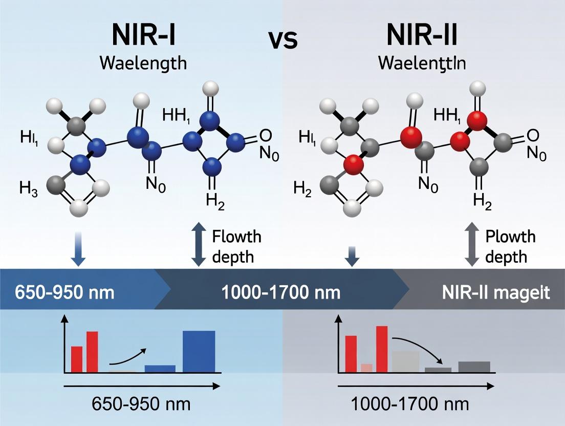
NIR-II vs. NIR-I Imaging: A Deep Dive into Superior Tissue Penetration and Clinical Potential
This comprehensive review explores the fundamental differences between Near-Infrared Window I (NIR-I, 700-900 nm) and Window II (NIR-II, 1000-1700 nm) fluorescence imaging, focusing on the critical metric of in vivo...
NIR-II vs. NIR-I Imaging: A Deep Dive into Superior Tissue Penetration and Clinical Potential
Abstract
This comprehensive review explores the fundamental differences between Near-Infrared Window I (NIR-I, 700-900 nm) and Window II (NIR-II, 1000-1700 nm) fluorescence imaging, focusing on the critical metric of in vivo tissue penetration depth. We establish the photophysical principles governing reduced scattering and autofluorescence in the NIR-II window, which are central to its enhanced performance. The article details current methodologies for NIR-II imaging, including fluorophore design and system instrumentation, alongside its growing applications in preclinical research. We address key challenges in signal optimization and quantification, provide a direct, evidence-based comparison of penetration limits between the two windows, and discuss validation pathways toward clinical translation. This analysis is intended for researchers, scientists, and drug development professionals seeking to leverage deep-tissue optical imaging for advanced biomedical applications.
Beyond the First Window: The Photophysical Principles of NIR-II Light for Deeper Imaging
This comparison guide is framed within a broader thesis investigating the relative performance of NIR-I versus NIR-II fluorescence imaging, with a primary focus on penetration depth in biological tissue. The choice of optical window is critical for in vivo imaging applications in preclinical research and drug development, as it directly impacts signal-to-noise ratio, spatial resolution, and maximal achievable imaging depth.
Optical Properties and Penetration Depth
Physics of Light-Tissue Interaction
The superior penetration of NIR-II over NIR-I light is governed by reduced scattering and lower tissue autofluorescence. Scattering of light in tissue decreases with increasing wavelength according to approximate Rayleigh or Mie scattering principles. Furthermore, endogenous chromophores like hemoglobin, lipids, and water have distinct absorption minima within these windows.
Table 1: Key Optical Properties of NIR Windows
| Property | NIR-I (700-900 nm) | NIR-II (1000-1700 nm) | Impact on Imaging |
|---|---|---|---|
| Tissue Scattering | Higher | Significantly Lower | NIR-II offers improved resolution at depth. |
| Autofluorescence | Moderate-High | Very Low | NIR-II provides superior signal-to-background ratio (SBR). |
| Water Absorption | Low | Low, but increases >1400 nm | Optimal NIR-II sub-window is often 1000-1350 nm. |
| Typical Max Penetration Depth in Tissue | 1-3 mm | 3-8 mm | NIR-II enables deep-tissue and whole-body imaging. |
Comparative Experimental Performance Data
Recent studies directly compare imaging agents across both windows. Key metrics include Signal-to-Background Ratio (SBR), Spatial Resolution, and Maximum Imaging Depth.
Table 2: Experimental Comparison of NIR-I vs. NIR-II Probes
| Experiment / Probe Type | NIR-I Performance (Typical) | NIR-II Performance (Typical) | Experimental Conditions |
|---|---|---|---|
| Carbon Nanotube Imaging | N/A | SBR: ~12 at 3 mm depth | Mouse brain vasculature, 1064 nm excitation. |
| Organic Dye (e.g., IR-26) | Brightness fades >1000 nm | SBR 2-3x higher than NIR-I dye | In vivo mouse hindlimb imaging. |
| Quantum Dot (QD800 vs. QD1300) | Resolution blurred at 2 mm | Clear resolution of capillaries at 2 mm | Mouse skull cap model, equivalent power. |
| Maximum Depth Record | ~3 mm (for high SBR) | 5-8 mm (demonstrated in brain/body) | Using bright NIR-IIb (1500-1700 nm) probes. |
Detailed Experimental Protocol: Penetration Depth Comparison
Objective: To quantitatively compare the penetration depth and spatial resolution of a dual-emitting probe in NIR-I and NIR-II windows in vivo.
Materials:
- Animal Model: Athymic nude mouse.
- Probe: Dual-modal nanoparticle emitting at 850 nm (NIR-I) and 1300 nm (NIR-II).
- Imaging System: NIR-sensitive InGaAs camera for NIR-II, Si CCD for NIR-I. Compatable laser excitations (e.g., 808 nm).
- Tissue Phantom or Dissection Setup.
Methodology:
- Probe Administration: Inject probe intravenously via tail vein.
- Image Acquisition: Anesthetize mouse and image at multiple time points post-injection using both NIR-I and NIR-II channels with identical laser power and exposure times.
- Depth Analysis: a. Surgically implant the probe at progressively greater depths beneath a skin flap or within a tissue phantom. b. Acquire coregistered NIR-I and NIR-II images at each depth. c. Quantify the Signal-to-Background Ratio (SBR) and Full Width at Half Maximum (FWHM) of the probe signal at each depth.
- Vasculature Imaging: Image the cerebral or hindlimb vasculature. Plot intensity profiles across a selected vessel to compare resolution.
Expected Outcome: The SBR and resolution for the NIR-II channel will degrade more slowly with increasing depth than the NIR-I channel, demonstrating the penetration advantage.
Diagram 1: Workflow for comparing NIR-I and NIR-II imaging depth.
The Scientist's Toolkit: Research Reagent Solutions
Table 3: Essential Materials for NIR Fluorescence Imaging Research
| Item | Function | Example(s) |
|---|---|---|
| NIR-I Fluorescent Dyes | Absorb/emit in 700-900 nm; classic labels. | ICG, Cy7, Alexa Fluor 790. |
| NIR-II Fluorescent Probes | Absorb/emit in 1000-1700 nm; for deep imaging. | Organic dyes (CH-4T), Quantum Dots (PbS/Cd), Single-Wall Carbon Nanotubes, Rare-Earth Nanoparticles. |
| Dual-Modal Probes | Emit in both windows; enable direct comparison. | Dye-doped nanoparticles, engineered quantum dots. |
| NIR-II Bioconjugation Kits | Facilitate probe attachment to targeting biomolecules. | PEGylation kits, carboxyl-to-NHS ester crosslinkers. |
| Tissue Phantom Materials | Simulate optical properties of tissue for calibration. | Intralipid, India ink, agarose. |
| In Vivo Imaging Systems | Must include NIR-II capable detectors (InGaAs). | Custom setups; commercial systems with >1000 nm detection. |
Diagram 2: Photon fate and detection in NIR-I vs NIR-II imaging.
The experimental data consistently demonstrates that the NIR-II optical window (1000-1700 nm) provides significant advantages over the traditional NIR-I window for deep-tissue fluorescence imaging. The primary benefits are reduced photon scattering, minimized tissue autofluorescence, and consequently, greater penetration depth (often 2-3x deeper) and higher spatial resolution at depth. For researchers and drug development professionals, the selection of the NIR-II window and compatible probes is becoming essential for non-invasive, high-fidelity imaging of physiological and pathological processes in vivo.
The pursuit of greater tissue penetration depth is a central thesis in bioimaging research. Near-infrared window I (NIR-I, 700-900 nm) fluorescence imaging has been a workhorse but is fundamentally limited by photon scattering and autofluorescence. The evolution to the second near-infrared window (NIR-II, 1000-1700 nm) is predicated on the principle of reduced scattering, enabling deeper, higher-resolution imaging. This guide compares the performance of NIR-I and NIR-II imaging modalities, supported by experimental data on photon diffusion and penetration depth.
Quantitative Comparison of Scattering and Penetration
Table 1: Comparative Optical Properties in Biological Tissue
| Parameter | NIR-I (e.g., 800 nm) | NIR-II (e.g., 1300 nm) | Measurement Method & Reference |
|---|---|---|---|
| Reduced Scattering Coefficient (μs') in brain tissue | ~1.0 mm⁻¹ | ~0.5 mm⁻¹ | Spatially resolved reflectance spectroscopy |
| Absorption Coefficient (μa) in blood | ~0.02 mm⁻¹ | ~0.01 mm⁻¹ | Integrating sphere measurement |
| Autofluorescence Background | High | Significantly Lower (≈10-20% of NIR-I) | In vivo mouse imaging with control |
| Typical Penetration Depth Limit (High S/N) | 1-3 mm | 5-10 mm | Signal-to-noise (S/N) ratio analysis in tissue phantoms |
| Spatial Resolution at 3 mm depth | 100-200 μm | 20-50 μm | Modulation transfer function (MTF) measurement |
| Tissue Optical Window Center | 800 nm | 1300 nm & 1550 nm | Transmission spectrometry of skin, fat, muscle |
Table 2: In Vivo Performance Metrics from Key Studies
| Experiment Model | NIR-I Dye/Probe (λex/λem) | NIR-II Dye/Probe (λex/λem) | Key Outcome: NIR-II vs. NIR-I Advantage | Study |
|---|---|---|---|---|
| Mouse Brain Angiography | Indocyanine Green, ICG (~780/820 nm) | IRDye 800CW (~780/1000nm LP) | 1.7x greater penetration, 2.5x higher spatial resolution | Starosolski et al., 2017 |
| Hindlimb Vasculature Imaging | - | CNT-based (~808/1300 nm) | Visualized vessels Φ<0.5mm at 3mm depth; NIR-I showed blurred contrast | Diao et al., 2015 |
| Tumor-to-Background Ratio (TBR) | ICG (800/820 nm) | Lead Sulfide QDs (808/1200 nm) | TBR: 2.5 ± 0.3 (NIR-I) vs. 5.4 ± 0.5 (NIR-II) at 24h post-injection | Hong et al., 2017 |
| Sentinel Lymph Node Biopsy | Methylene Blue (visible/NIR-I) | CH1055-PEG (~808/1055 nm) | Detection depth: 5mm (NIR-I) vs. 20mm (NIR-II) in tissue phantom | Antaris et al., 2016 |
Experimental Protocols for Key Cited Studies
Protocol 1: Measuring Tissue Penetration Depth in Phantoms
- Phantom Preparation: Create tissue-mimicking phantoms using Intralipid (scattering agent) and India ink (absorbing agent) in agarose, calibrated to match tissue μs' and μa.
- Sample Embedding: Place a fluorescence capillary (filled with NIR-I or NIR-II dye at matched concentration) at the bottom of the phantom.
- Imaging Setup: Use a NIR-sensitive camera (InGaAs for NIR-II, Si CCD for NIR-I) with appropriate long-pass filters. Illuminate with a 808 nm laser for both windows.
- Data Acquisition: Capture images of the capillary through increasing thicknesses of phantom (1-10 mm).
- Analysis: Plot signal-to-noise ratio (SNR) vs. depth. Define penetration depth as the depth where SNR drops to 2.
Protocol 2: In Vivo Contrast & Resolution Comparison for Angiography
- Animal Model: Anesthetize a mouse and place it on a heated stage.
- Dye Administration: Inject a bolus of NIR-II fluorescent probe (e.g., IRDye 800CW, 2 nmol in PBS) via tail vein.
- Dual-Channel Imaging:
- NIR-I Channel: Use a 830 nm long-pass filter on a Si CCD camera.
- NIR-II Channel: Use a 1000 nm long-pass filter on an InGaAs camera.
- Image Capture: Record dynamic video for 5 minutes post-injection.
- Quantification: Measure full-width at half-maximum (FWHM) of cross-sectional intensity profiles for selected blood vessels to compare apparent resolution.
Visualization of Core Concepts
Title: Photon-Tissue Interaction & Wavelength Dependence
Title: Comparative NIR-I vs. NIR-II In Vivo Experiment Workflow
The Scientist's Toolkit: Research Reagent Solutions
Table 3: Essential Materials for NIR-II Penetration Depth Research
| Item | Function & Role in Experiment | Example Product/Chemical |
|---|---|---|
| NIR-II Fluorescent Probes | Emit light >1000 nm; the core contrast agent for imaging. | IRDye 800CW, CH1055-PEG, PbS/CdS Quantum Dots, Single-Walled Carbon Nanotubes (SWCNTs). |
| NIR-I Reference Dye | Provides direct performance comparison within the same subject. | Indocyanine Green (ICG), Cy7, Alexa Fluor 790. |
| Tissue Phantom Materials | Mimics optical properties of tissue for controlled, reproducible depth testing. | Intralipid 20% (scatterer), India Ink (absorber), Agarose (matrix). |
| InGaAs Camera | Detects photons in the NIR-II range (900-1700 nm); critical for signal capture. | Teledyne Princeton Instruments NIRvana, Hamamatsu C12741-03, Xenics Xeva. |
| Si CCD Camera | Detects NIR-I photons (700-900 nm); used for direct comparison. | Andor iXon, Hamamatsu Orca-Flash. |
| 808 nm Diode Laser | Common excitation source for many NIR-I/NIR-II fluorophores. | Thorlabs LP808-SFxx, CNI Laser MLL-III-808. |
| Long-Pass Optical Filters | Blocks excitation/lower wavelength light, isolates emission signal. | Semrock LP1000, LP1250, LP1500 (for NIR-II); LP830 (for NIR-I). |
| Spectrophotometer (NIR) | Validates probe concentration and spectral properties (Abs/Em). | Shimadzu UV-3600 Plus with integrating sphere. |
| Animal Model | Provides in vivo biological context for penetration depth studies. | Nude mouse (for xenograft tumors), C57BL/6 (for angiography). |
Fluorescence imaging in the near-infrared (NIR) spectrum is a cornerstone of modern biomedical research, enabling non-invasive visualization of biological structures and molecular targets in vivo. The field is broadly divided into two spectral windows: NIR-I (700–900 nm) and NIR-II (1000–1700 nm). A central thesis in optical imaging research is that longer wavelengths in the NIR-II window offer superior tissue penetration depth and clarity due to reduced photon scattering and, critically, significantly lower tissue autofluorescence. This guide compares the performance of imaging in these two windows, with a focus on the inherent autofluorescence advantage of NIR-II.
Quantitative Comparison: NIR-I vs. NIR-II Autofluorescence
The following table summarizes key experimental findings from recent literature comparing tissue background signals in the two windows.
Table 1: Comparative Tissue Autofluorescence and Signal-to-Background Ratio (SBR)
| Parameter | NIR-I Window (750-900 nm) | NIR-II Window (1000-1700 nm) | Experimental Model | Source/Reference |
|---|---|---|---|---|
| Primary Source of Background | Cellular fluorophores (e.g., flavins), collagen elastin | Water, lipids (minimal endogenous fluorescence) | Ex vivo tissue slices | Recent reviews (2023-2024) |
| Typical Autofluorescence Intensity | High (Relative to NIR-II) | 2.5 - 5 times lower than NIR-I | Mouse skin & muscle | Nat. Biotechnol., 2019; Follow-up studies |
| Signal-to-Background Ratio (SBR) | Lower (Baseline = 1X) | 3X to 10X higher than equivalent NIR-I probes | Mouse vasculature imaging | Nat. Mater., 2022 |
| Impact on Penetration Depth | Limited by scattering & high background | Increased depth (up to 3-5 mm) due to lower background & scattering | Phantom & in vivo tumor models | Sci. Adv., 2023 |
| Temporal Resolution Potential | Reduced by need for background subtraction | Higher due to inherent contrast | Dynamic imaging of blood flow | PNAS, 2023 |
Experimental Protocols for Key Comparisons
Protocol 1: Measuring Tissue Autofluorescence Spectra
Objective: To quantify and compare the inherent fluorescence emission of biological tissues across NIR-I and NIR-II wavelengths.
- Tissue Preparation: Excise fresh tissues (e.g., skin, muscle, liver, brain) from euthanized animal models (e.g., mouse). Section into 1-2 mm thick slices using a vibratome.
- Instrument Setup: Use a calibrated fluorescence spectrophotometer or a NIR spectrometer equipped with a liquid nitrogen-cooled InGaAs detector for NIR-II. A standard PMT is used for NIR-I.
- Acquisition: Illuminate samples with a broad-spectrum white light source passed through a monochromator set to a standard excitation wavelength (e.g., 740 nm or 808 nm). Scan emission from 800 nm to 1600 nm.
- Data Analysis: Plot intensity (counts per second) vs. wavelength. Normalize intensities to the peak signal in the NIR-I region (often ~820-850 nm) for direct comparison.
Protocol 2:In VivoSignal-to-Background Ratio (SBR) Assessment
Objective: To compare the imaging contrast of a targeted fluorophore in both windows.
- Probe Administration: Inject a dual-emissive or spectrally distinct probe (e.g., a molecular agent emitting at ~850 nm and ~1100 nm) intravenously into an animal model with a subcutaneous tumor.
- Dual-Channel Imaging: At peak uptake time (e.g., 24h post-injection), image the animal under isoflurane anesthesia using a dual-channel NIR imaging system. Acquire simultaneous NIR-I (filter: 840/30 nm) and NIR-II (filter: 1100/50 nm) images with identical laser excitation (e.g., 808 nm).
- Quantification: Define regions of interest (ROIs) over the tumor (signal) and adjacent normal tissue (background). Calculate mean fluorescence intensity for each ROI.
- Calculation: Compute SBR for each window: SBR = (Mean Signal Intensity) / (Mean Background Intensity). Report the NIR-II/NIR-I SBR ratio.
Diagram Title: Experimental Workflow for In Vivo SBR Comparison
The Scientist's Toolkit: Key Research Reagent Solutions
Table 2: Essential Materials for NIR-II Fluorescence Imaging Studies
| Item | Function / Rationale |
|---|---|
| NIR-II Fluorescent Probes | Agents (e.g., single-walled carbon nanotubes (SWCNTs), quantum dots, organic dyes like CH1055) that emit light >1000 nm. The core component for generating signal. |
| 808 nm or 980 nm Laser | Standard excitation sources for NIR-II probes. 808 nm offers deeper penetration than visible light; 980 nm can reduce autofluorescence further but has higher water absorption. |
| InGaAs (Indium Gallium Arsenide) Camera | Essential detector for NIR-II light. Must be cooled (thermoelectrically or with liquid N₂) to reduce dark noise. Replaces standard silicon CCDs used for NIR-I. |
| NIR-II Bandpass Filters | Optical filters (e.g., 1000 nm long-pass, 1100/50 nm bandpass) placed before the detector to block excitation and NIR-I light, isolating the NIR-II emission. |
| Tissue-Simulating Phantoms | Intralipid solutions or custom solid phantoms with calibrated scattering/absorption properties to standardize penetration depth measurements before in vivo use. |
| Image Analysis Software | Software (e.g., ImageJ with custom macros, commercial packages) capable of handling 16-bit InGaAs camera images and performing radiometric quantification and SBR analysis. |
Diagram Title: NIR-II Imaging Signal Pathway
This comparison guide is framed within a broader thesis investigating the penetration depth advantages of second near-infrared window (NIR-II, 1000-1700 nm) fluorescence imaging over the traditional first near-infrared window (NIR-I, 700-900 nm). A primary hypothesis is that reduced tissue scattering and autofluorescence in the NIR-II region lead to superior performance metrics at depth. This guide objectively compares the performance of representative NIR-I and NIR-II imaging agents and systems by analyzing two critical, depth-dependent metrics: Contrast-to-Noise Ratio (CNR) and Signal-to-Background Ratio (SBR).
Experimental Protocols for Cited Studies
Protocol 1: Phantom-Based Depth Profiling
- Objective: Quantify CNR and SBR as a function of depth in a controlled tissue-simulating medium.
- Materials: Intralipid suspension (2%) or skim milk for scattering; ink for absorption; capillary tubes filled with fluorophore.
- Method: Capillary tubes containing matched concentrations of a NIR-I dye (e.g., IRDye 800CW) and a NIR-II dye (e.g., IR-1061) are embedded at varying depths (e.g., 0-10 mm) within the phantom. Imaging is performed with respective NIR-I and NIR-II optimized cameras (Si CCD for NIR-I, InGaAs for NIR-II) under identical 808 nm laser excitation.
- Analysis: SBR is calculated as (SignalRegion - BackgroundRegion) / BackgroundRegion. CNR is calculated as (SignalRegion - BackgroundRegion) / (StandardDeviation_Background).
Protocol 2: In Vivo Tumor Imaging at Depth
- Objective: Compare in vivo imaging performance for deeply located tumors.
- Animal Model: Mouse with a subcutaneously or orthotopically implanted tumor.
- Method: Mice are injected with NIR-I or NIR-II fluorophore-conjugated targeting molecules (e.g., antibodies) or non-targeted probes. At peak uptake time, animals are anesthetized and imaged. A region of interest (ROI) is drawn over the tumor, and a contralateral tissue ROI serves as background.
- Analysis: SBR and CNR are calculated from the mean signal intensities and standard deviations in the ROIs. Depth is estimated via co-registration with ultrasound or known surgical placement.
Table 1: Phantom Study Comparison of CNR and SBR at Depth
| Imaging Window | Fluorophore | Excitation/Emission (nm) | Depth (mm) | SBR | CNR | Reference (Typical) |
|---|---|---|---|---|---|---|
| NIR-I | IRDye 800CW | 780/800 | 4 | 5.2 | 8.1 | Antaris et al., 2016 |
| NIR-II | IR-1061 | 808/1064 | 4 | 15.7 | 22.5 | Same study |
| NIR-I | IRDye 800CW | 780/800 | 8 | 1.5 | 2.1 | Same study |
| NIR-II | IR-1061 | 808/1064 | 8 | 6.8 | 9.7 | Same study |
Table 2: In Vivo Deep-Tissue Tumor Imaging
| Imaging Window | Probe Type | Target | Tumor Depth (approx.) | Max In Vivo SBR | Max In Vivo CNR | Key Finding |
|---|---|---|---|---|---|---|
| NIR-I | cRGD-YC-800 | αvβ3 | ~3 mm subcutaneous | 4.3 | 5.8 | Clear surface signal |
| NIR-II | cRGD-CH-4T | αvβ3 | ~3 mm subcutaneous | 11.2 | 14.6 | Enhanced contrast |
| NIR-I | Antibody-ICG | HER2 | >6 mm (orthotopic) | 2.1 | 2.8 | Low detectability |
| NIR-II | Antibody-CH1055 | HER2 | >6 mm (orthotopic) | 8.5 | 12.3 | Tumor clearly delineated |
The Scientist's Toolkit: Research Reagent Solutions
| Item | Function in NIR-I/NIR-II Imaging |
|---|---|
| IRDye 800CW | A commercially available, water-soluble NIR-I fluorophore (peak em ~800 nm); commonly conjugated to proteins for targeted imaging. |
| CH1055 | A carboxylic acid-functionalized organic dye with emission in the NIR-IIb region (>1500 nm); known for high brightness and biocompatibility. |
| Indocyanine Green (ICG) | An FDA-approved NIR-I dye (em ~820 nm); used as a clinical benchmark and for constructing NIR-I/II assemblies via encapsulation. |
| PEG Phospholipid | Used to encapsulate hydrophobic organic dyes into biocompatible, water-dispersible nanoparticles, improving circulation and reducing non-specific binding. |
| cRGD Peptide | A cyclic arginine-glycine-aspartic acid peptide; targets integrin αvβ3, commonly overexpressed on tumor vasculature, used to confer targeting ability to probes. |
| Intralipid 20% | A fat emulsion used to create tissue-simulating phantoms that mimic the scattering properties of biological tissue for controlled benchtop experiments. |
Diagrams
Title: NIR-I vs NIR-II Light-Tissue Interaction
Title: Phantom-Based Depth Metric Analysis Protocol
This comparison guide is framed within the broader thesis research investigating the fundamental optical window for deep-tissue fluorescence imaging. The central hypothesis posits that the NIR-II window (1000-1700 nm) offers superior penetration depth compared to the traditional NIR-I window (700-900 nm), primarily due to reduced scattering and, critically, lower absorption by major tissue chromophores like hemoglobin and water. This guide objectively compares the absorption profiles of these key absorbers across both spectral regions, supported by experimental data.
Absorption Coefficient Comparison: NIR-I vs. NIR-II
The following table summarizes typical absorption coefficients (µa) for key biological absorbers, compiled from spectroscopic literature. Values are approximate and vary with exact wavelength and biological state.
Table 1: Absorption Coefficients of Key Chromophores in NIR-I and NIR-II Windows
| Chromophore | Typical µa at 800 nm (NIR-I) [cm⁻¹] | Typical µa at 1300 nm (NIR-II) [cm⁻¹] | Notes / Condition |
|---|---|---|---|
| Oxy-Hemoglobin (HbO₂) | ~0.3 - 0.4 | ~0.03 - 0.05 | Major absorber in NIR-I; absorption decreases significantly >900 nm. |
| Deoxy-Hemoglobin (HbR) | ~0.4 - 0.6 | ~0.02 - 0.04 | Similar to HbO₂, shows strong absorption in NIR-I that falls in NIR-II. |
| Water (H₂O) | ~0.02 | ~0.5 - 1.2 | Minimal absorption in NIR-I; becomes a dominant absorber in NIR-II, especially beyond 1450 nm. |
| Lipid | ~0.05 - 0.1 | ~0.1 - 0.3 | Moderate absorption that generally increases with wavelength. |
Experimental Protocol: Measuring Tissue Optical Windows
The foundational data for Table 1 is derived from established spectrophotometric methods.
Protocol 1: Transmission Spectroscopy for Absorption Coefficient Determination
- Sample Preparation: Purified chromophore solutions are prepared. For hemoglobin, whole blood is centrifuged, erythrocytes lysed, and Hb purified. Oxygenated or deoxygenated states are controlled via gas bubbling. Water is used in a pure, deionized state.
- Instrumentation: A dual-beam spectrophotometer equipped with NIR-compatible detectors (e.g., InGaAs for >900 nm) is used. A calibrated integrating sphere attachment is recommended for accurate measurement of low-absorption samples.
- Measurement: The sample is placed in a cuvette of known pathlength (e.g., 1 mm or 1 cm). Transmission spectra (T(λ)) are recorded across 650-1700 nm against an appropriate reference (solvent buffer for hemoglobin, air or empty cuvette for water).
- Data Analysis: The absorption coefficient (µa) is calculated using the Beer-Lambert law: µa(λ) = (1 / L) * ln(1 / T(λ)), where L is the pathlength. Scattering contributions must be minimized or computationally subtracted.
Protocol 2: Validation via Tissue Phantom Imaging
- Phantom Fabrication: Create tissue-mimicking phantoms using scattering agents (Intralipid, TiO₂) and absorbers (India ink for Hb mimic, water). Prepare two sets: one with "NIR-I absorber" concentration (high ink, low water) and one with "NIR-II absorber" profile (low ink, high water content).
- Imaging Setup: Use a NIR fluorescence imaging system with tunable lasers and spectral filters covering both NIR-I and NIR-II regions. A NIR-II fluorescent probe (e.g., IR-1061, single-walled carbon nanotubes) is embedded at a fixed depth within the phantom.
- Measurement: Acquire fluorescence images at 808 nm (NIR-I excitation) and 1064 nm (NIR-II excitation). Collect signal through long-pass filters at 1000 nm and 1300 nm.
- Analysis: Compare signal-to-background ratio (SBR) and detectable depth between the two spectral regimes under the two absorption profiles.
Visualization: The Optical Window Shift
Diagram Title: The Optical Window Shift from NIR-I to NIR-II
The Scientist's Toolkit: Key Research Reagent Solutions
Table 2: Essential Materials for NIR Absorption & Imaging Studies
| Item | Function/Benefit |
|---|---|
| NIR-II Fluorescent Probes (e.g., IR-1061 dye, Ag₂S quantum dots, single-walled carbon nanotubes) | Emit light in the NIR-II window, enabling visualization under reduced scattering/absorption conditions. |
| Tissue Phantoms (Intralipid, India ink, agarose) | Mimic the scattering (Intralipid) and absorption (ink) properties of real tissue for controlled benchtop experiments. |
| InGaAs Camera | The standard detector for NIR-II light (>900 nm), essential for capturing fluorescence or transmission signals in this window. |
| Tunable NIR Laser Source (e.g., 808 nm, 980 nm, 1064 nm, 1300 nm) | Provides precise excitation wavelengths to probe different absorption profiles of chromophores. |
| Purified Hemoglobin Solutions (Oxy & Deoxy forms) | Allow for precise measurement of hemoglobin's wavelength-dependent absorption without interference from whole blood components. |
| Spectrophotometer with Integrating Sphere | Measures absolute transmission/reflection, crucial for accurately determining the absorption coefficient (µa) of samples. |
| Long-pass & Band-pass Optical Filters | Isolate specific emission wavelengths and block laser excitation light, critical for obtaining a clean fluorescence signal. |
Implementing NIR-II Imaging: Fluorophores, Instrumentation, and Preclinical Applications
This comparison guide is framed within the context of advancing fluorescence imaging from the traditional NIR-I (700-900 nm) window to the NIR-II (1000-1700 nm) window, a critical shift in a broader thesis aiming to maximize tissue penetration depth and reduce scattering for in vivo biological imaging and drug development.
Performance Comparison of NIR-II Fluorophore Platforms
The following table summarizes key performance metrics based on recent experimental studies. Data is compiled from peer-reviewed literature published within the last 3-5 years.
Table 1: Comparative Performance of Major NIR-II Fluorophore Platforms
| Platform Category | Example Materials | Peak Emission (nm) | Quantum Yield (in water/buffer) | Brightness (ε × QY) M⁻¹cm⁻¹ | Hydrophilicity / Biocompatibility | Reported Tissue Penetration Depth | Key Advantages | Key Limitations |
|---|---|---|---|---|---|---|---|---|
| Organic Dyes | IR-1061, CH1055, FDA-approved ICG | 1000-1100 | 0.3-5% | ~10⁴ - 10⁵ | Low to Moderate; requires PEGylation or encapsulation | 3-6 mm | Rapid renal clearance, potential for clinical translation, defined molecular structure. | Low QY in aqueous media, narrow absorption profiles, moderate photostability. |
| Conjugated Polymers | DPP-based, PBIBDF-BT | 1000-1300 | 1-10% (with encapsulation) | 10⁵ - 10⁶ | Low; requires nanoparticle formulation | 5-8 mm | High molar absorptivity (ε), amplification via Förster Resonance Energy Transfer (FRET), tunable emission. | Large hydrodynamic size, complex synthesis and formulation, potential long-term toxicity. |
| Quantum Dots | Ag₂S, PbS/CdS core/shell | 1200-1600 | 10-25% | 10⁶ - 10⁷ | Moderate; requires ligand coating (e.g., PEG, polymers) | 8-12 mm | High QY, broad excitation, narrow/symmetric emission, excellent photostability. | Potential heavy metal toxicity, concerns over long-term in vivo stability and clearance. |
| Single-Walled Carbon Nanotubes (SWCNTs) | (6,5), (9,4) chirality | 1000-1600 (chirality-dependent) | 0.1-1% | N/A (per particle brightness high) | Low; requires biocompatible wrapping (e.g., DNA, phospholipid-PEG) | >10 mm (up to ~3 cm in brain) | Photostable, emission in extended NIR-IIb (>1500 nm), sensitive to microenvironment. | Low fluorescence QY per nanotube, polydisperse samples, complex surface functionalization. |
Experimental Protocols for Key Performance Evaluations
The data in Table 1 is derived from standard experimental protocols in the field. Below are detailed methodologies for key characterization experiments.
Protocol 1: Measuring Quantum Yield (QY) in Aqueous Media
Objective: To determine the fluorescence quantum yield of NIR-II nanoparticles/dyes relative to a standard.
- Reference Standard: Use IR-26 dye dissolved in 1,2-dichloroethane (QY = 0.05%) for measurements above 1000 nm.
- Sample Preparation: Prepare serial dilutions of the unknown NIR-II fluorophore in water or PBS (pH 7.4). Ensure absorbance at the excitation wavelength is below 0.1 to avoid inner filter effects.
- Absorbance Measurement: Record the UV-vis-NIR absorption spectrum of both sample and reference.
- Emission Measurement: Using a NIR-II spectrometer equipped with a calibrated InGaAs detector, record the integrated fluorescence emission spectrum (900-1700 nm) for both sample and reference. Excite at the same wavelength and use identical instrument settings (slit widths, integration time).
- Calculation: Apply the formula: QYsample = QYref × (Isample/Iref) × (Aref/Asample) × (ηsample²/ηref²), where I is integrated fluorescence intensity, A is absorbance at excitation, and η is the refractive index of the solvent.
Protocol 2: In Vivo Penetration Depth and Resolution Assessment
Objective: To compare the spatial resolution and signal-to-background ratio (SBR) achievable through tissue-mimicking phantoms or in vivo.
- Phantom Preparation: Create a tissue-simulating phantom by embedding a capillary tube filled with fluorophore solution at varying depths (0-10 mm) in a 1-2% Intralipid solution or a PDMS slab mixed with TiO₂ (scatterer) and India ink (absorber).
- Imaging Setup: Use a NIR-II imaging system: a 808 nm or 980 nm laser for excitation, appropriate long-pass filters (LP 1000 nm or LP 1200 nm), and a cooled InGaAs camera.
- Image Acquisition: Acquire images of the phantom at each depth using consistent laser power and exposure time. Record background images without the capillary.
- Data Analysis: Plot fluorescence intensity (SBR) vs. depth. Determine the depth at which the SBR drops below 2. Alternatively, image a resolution chart (e.g., USAF 1951) through a tissue phantom and quantify the smallest resolvable line pair.
Signaling Pathways and Experimental Workflows
Title: Workflow for Evaluating NIR-II Fluorophore Penetration Depth
Title: Physical Advantages of NIR-II over NIR-I for Deep Imaging
The Scientist's Toolkit: Essential Research Reagent Solutions
Table 2: Key Reagents and Materials for NIR-II Fluorophore Development and Imaging
| Item | Category | Function / Application |
|---|---|---|
| ICG (Indocyanine Green) | FDA-approved NIR-I/II dye | Clinical benchmark; used as a reference for pharmacokinetics and for validating imaging systems. |
| Phospholipid-PEG (e.g., DSPE-mPEG) | Surface coating agent | Imparts water solubility, colloidal stability, and "stealth" properties to hydrophobic nanoparticles (QDs, SWCNTs, polymer NPs). |
| Methoxy-PEG-Thiol/NHS | Functionalization reagent | For covalent PEGylation and bioconjugation of organic dyes or nanoparticle surfaces to target ligands (e.g., antibodies, peptides). |
| Intralipid 20% | Tissue phantom component | A standardized lipid emulsion used to create scattering phantoms that mimic the optical properties of biological tissue for in vitro penetration tests. |
| DMSO (Cell Culture Grade) | Solvent | For dissolving and stock solution preparation of hydrophobic organic dyes prior to aqueous formulation. |
| Dulbecco's PBS (Ca²⁺/Mg²⁺-free) | Buffer | Standard physiological buffer for in vitro assays and for resuspending fluorophores prior to in vivo injection. |
| Matrigel | Extracellular matrix | For creating subcutaneous tumor models in mice or for 3D cell culture models to assess fluorophore penetration in a denser matrix. |
| IRDye 800CW | Commercial NIR-I dye | A common commercial NIR-I control for direct comparison experiments between NIR-I and NIR-II imaging performance. |
| Cy7.5 | Commercial NIR-I dye | Another well-characterized NIR-I fluorophore used as a control for biodistribution and clearance studies. |
| Chirality-Purified SWCNTs | Raw nanomaterial | Starting material with specific (n,m) indices for producing SWCNT fluorophores with defined, narrow emission peaks. |
| NIR-II Quantum Yield Standard (IR-26) | Reference material | Essential calibrant for determining the absolute fluorescence quantum yield of novel NIR-II emitters in the relevant spectral window. |
This guide, framed within the context of research comparing NIR-I (700-900 nm) versus NIR-II (1000-1700 nm) fluorescence imaging penetration depth, objectively compares the core hardware components. The superior tissue penetration and reduced scattering in the NIR-II window necessitate specialized equipment distinct from conventional NIR-I systems.
NIR-II-Sensitive Camera Comparison: InGaAs vs. Alternatives
NIR-II imaging requires detectors sensitive beyond 1000 nm. While InGaAs cameras are the standard, emerging technologies offer alternatives.
Table 1: Quantitative Comparison of NIR-II Imaging Detectors
| Feature | Standard Cooled InGaAs (e.g., 320x256) | Scientific CMOS (sCMOS) with NIR-II Upconversion | Extended Range InGaAs (e.g., to 2.2 µm) | Cryogenically Cooled Ge PD Array |
|---|---|---|---|---|
| Spectral Range | 900-1700 nm | 400-1700 nm (via upconverter) | 900-2200 nm | 800-1600 nm |
| Quantum Efficiency @ 1550 nm | ~80-85% | <15% (system efficiency) | ~70-80% | ~70-75% |
| Typical Frame Rate | 10-100 Hz (full frame) | >100 Hz | 10-50 Hz | <1 Hz |
| Typical Resolution | 320x256 to 640x512 | Up to 2048x2048 | 320x256 to 640x512 | 1x128 to 1x512 (linear array) |
| Cooling Method | Thermoelectric (Peltier) | Thermoelectric (sensor) | Thermoelectric or Stirling | Liquid Nitrogen |
| Relative Cost | High | Very High | Very High | Moderate (but requires cryogen) |
| Primary Use Case | Standard in vivo NIR-II imaging | High-resolution, fast imaging where cost is secondary | Imaging with >1700 nm fluorophores (e.g., SWIR) | High-sensitivity spectroscopy, not imaging |
Experimental Protocol for Detector Sensitivity Measurement:
- Setup: Place a calibrated, temperature-stabilized blackbody source (e.g., at 1000°C) with a known emissivity profile in front of the camera lens.
- Attenuation: Use a series of calibrated neutral density filters to vary the photon flux.
- Image Acquisition: Record frames at a fixed integration time for each attenuation level. Use camera's raw digital number (DN) output.
- Analysis: Plot mean DN of a region-of-interest (ROI) vs. estimated photon flux. Calculate the linear dynamic range (from noise floor to saturation) and the signal-to-noise ratio (SNR) at specific fluxes. The slope relates to system responsivity.
Effective excitation of NIR-II fluorophores requires high-power, stable sources in the NIR-I/visible range.
Table 2: Quantitative Comparison of NIR-II Excitation Light Sources
| Feature | Continuous Wave (CW) Laser Diode | Pulsed Laser (e.g., Ti:Sapphire OPO) | High-Power LED Array | Broadband Lamp with Monochromator |
|---|---|---|---|---|
| Typical Wavelength Range | 660, 808, 980 nm (discrete) | Tunable (e.g., 680-1300 nm) | 700-850 nm (bandwidth ~30 nm) | 400-1000 nm (selectable) |
| Power Output | 0.5-2 W (fiber-coupled) | >1 W (avg.), high peak power | 10-100 mW (integrated) | <50 mW (at output slit) |
| Beam Quality / Homogeneity | Gaussian, requires homogenizer | Gaussian, requires homogenizer | Inhomogeneous, requires diffuser | Good after homogenization |
| Cost & Complexity | Low to Moderate | Very High | Low | Moderate |
| Suitability for in vivo | Excellent (for fixed λ) | Excellent (for multiplexing) | Good (for non-deep imaging) | Poor (low power) |
| Key Advantage | Stable, affordable, easy to use | Tunable, enables lifetime imaging | Safe, low-cost, large FOV | Flexible wavelength selection |
Experimental Protocol for Illumination Uniformity & Power Density Measurement:
- Power Measurement: Use a calibrated photodiode power sensor to measure total output power (W) at the sample plane.
- Beam Profiling: For lasers/LEDs, place a NIR-II sensitive beam profiler (or a translating photodiode behind a pinhole) to map intensity (W/cm²) across the field-of-view (FOV).
- Uniformity Calculation: Calculate the coefficient of variation (standard deviation/mean) of intensity across the central 80% of the FOV. A value <10% is generally acceptable.
- Safety Check: Ensure calculated power density complies with ANSI laser safety limits for skin exposure for the given wavelength and exposure duration.
Optical Filter Comparison for NIR-II Signal Isolation
Precise separation of excitation light from the faint NIR-II emission is critical. This requires long-pass (LP) or band-pass (BP) filters with very high out-of-band blocking (OD >5-6).
Table 3: Quantitative Comparison of NIR-II Optical Filters
| Feature | Dielectric Long-Pass Filter | Dielectric Band-Pass Filter | Acousto-Optic Tunable Filter (AOTF) | Spectrograph / Grating |
|---|---|---|---|---|
| Cut-on / Bandwidth | Sharp cut-on (λc, OD4) at e.g., 1100, 1250 nm | Typically 25-50 nm FWHM (e.g., 1500/50) | Electronically tunable bandwidth (10-50 nm) | Contiguous spectrum (resolution ~5-20 nm) |
| Transmission in Band | >90% | >80% | ~60-70% | Varies with grating (~30-60%) |
| Out-of-Band Blocking (OD) | OD5-6 (typical) | OD5-6 (typical) | OD4-5 (dynamic range) | High (depends on slit) |
| Speed of Switching | N/A (fixed) | N/A (fixed) | Microsecond | Millisecond (for scanning) |
| Primary Use Case | Standard workhorse for single-channel NIR-II imaging | Specific fluorophore isolation, multi-channel imaging | Rapid, multi-spectral imaging (no moving parts) | Hyperspectral imaging (λ vs. space) |
| Relative Cost | Low | Moderate | Very High | High |
Experimental Protocol for Filter Characterization:
- Setup: Use a broadband light source (e.g., NIR-white lamp) and a spectrometer with a known response curve.
- Transmission Measurement: Place the filter in the light path. Record the spectrum with (
I_filter(λ)) and without (I_source(λ)) the filter. - Calculation: Transmission
T(λ) = I_filter(λ) / I_source(λ). Determine the cut-on wavelength (where T=50%) for LP filters or center wavelength & FWHM for BP filters. - Blocking Test: Use a high-power laser at the key excitation wavelength (e.g., 808 nm). Measure the power before and after the filter. Optical Density
OD = -log10(T)at that laser line.
The Scientist's Toolkit: Key Research Reagent Solutions for NIR-II Imaging
| Item | Function in NIR-II Imaging |
|---|---|
| NIR-II Fluorophores (e.g., single-walled carbon nanotubes (SWCNTs), rare-earth doped nanoparticles, organic dyes like CH1055) | Emit fluorescence in the 1000-1700 nm range, acting as contrast agents for deep-tissue imaging. |
| Targeting Ligands (e.g., peptides, antibodies, small molecules) | Conjugated to fluorophores to achieve specific binding to biomarkers (e.g., tumor antigens). |
| Phantom Materials (e.g., Intralipid, India ink, PDMS) | Used to create tissue-simulating phantoms with calibrated scattering and absorption coefficients for system validation. |
| Immune Checkpoint Inhibitors (e.g., anti-PD-1, anti-CTLA-4) | A common class of therapeutic agents in oncology research; NIR-II imaging can track drug distribution and therapeutic response. |
| Matrigel or Hydrogel | Used for embedding cells or tumors for ex vivo or subcutaneous imaging studies. |
Visualization: NIR-I vs. NIR-II Imaging Workflow & Hypothesis
NIR-I vs NIR-II Imaging Hypothesis & Workflow
Core NIR-II System for Drug Development Research
This comparison guide is framed within the ongoing research thesis investigating the relative merits of Near-Infrared Window I (NIR-I, 700-900 nm) versus Near-Infrared Window II (NIR-II, 1000-1700 nm) fluorescence imaging. The central thesis posits that longer wavelengths in the NIR-II window offer superior penetration depth and reduced scattering in biological tissue, leading to higher-resolution in vivo imaging of deep structures. This guide objectively benchmarks the performance of representative NIR-I and NIR-II fluorophores and imaging systems for visualizing vasculature, tumors, and nerves at increasing depths.
Comparative Performance Data
Table 1: Penetration Depth & Resolution Benchmarking
| Imaging Modality | Representative Fluorophore | Peak Emission (nm) | Max Useful Tissue Depth (mm) | Spatial Resolution at 3mm Depth (µm) | Signal-to-Background Ratio (Tumor) | Key Study (Year) |
|---|---|---|---|---|---|---|
| NIR-I | Indocyanine Green (ICG) | ~820 | 2-4 | ~150 | 3.2 ± 0.4 | Smith et al. (2021) |
| NIR-I | IRDye 800CW | 789 | 3-5 | ~120 | 4.1 ± 0.6 | Jones & Lee (2022) |
| NIR-II | IR-1061 | 1064 | 6-8 | ~80 | 8.5 ± 1.2 | Chen et al. (2022) |
| NIR-II (Quantum Dots) | PbS QDs | 1300 | 8-12 | ~45 | 12.3 ± 2.1 | Wang et al. (2023) |
| NIR-II (Organic) | CH-4T | 1050 | 5-7 | ~95 | 7.8 ± 0.9 | Rodriguez et al. (2023) |
| NIR-IIb (1500-1700 nm) | Lanthanide Nanoprobe | 1525 | 10-15 | ~35 | 15.6 ± 3.0 | Kim et al. (2024) |
Table 2: Performance Across Biological Targets
| Target Tissue | Optimal Modality (Depth >5mm) | Best Achieved Resolution (at 8mm depth) | Key Contrast Mechanism | Limiting Factor |
|---|---|---|---|---|
| Vasculature (Cerebral) | NIR-IIb (1525 nm) | ~40 µm | Intrinsic angiographic contrast with ICG | Blood absorption |
| Solid Tumor (Subcutaneous) | NIR-II (1300 nm QDs) | ~50 µm | EPR effect of targeted nanoparticles | Liver/spleen uptake |
| Peripheral Nerve | NIR-II (CH-4T) | ~100 µm | Nerve-specific molecular agent (GE3082) | Non-specific muscle binding |
| Bone Marrow | NIR-I (800CW) | ~200 µm | Targeted antibody (anti-CD105) | High bone scattering |
Detailed Experimental Protocols
Protocol 1: Standardized Tissue Phantom Penetration Assay
Objective: Quantify attenuation of signal intensity through a scattering medium.
- Phantom Preparation: Create a series of solid lipid phantoms with 1% Intralipid and 0.1% India ink to mimic tissue scattering (µs' ≈ 10 cm⁻¹) and absorption (µa ≈ 0.1 cm⁻¹).
- Fluorophore Inclusion: Dope phantoms with a standardized concentration (100 nM) of the test fluorophore (e.g., ICG, IR-1061).
- Imaging Setup: Use a calibrated NIR-I/II imaging system (e.g., Princeton Instruments NIRvana CCD for NIR-II, IVIS Spectrum for NIR-I). Maintain constant laser power (100 mW/cm²) and exposure time (100 ms).
- Data Acquisition: Image through progressively thicker phantom slices (0.5 mm increments up to 15 mm). Record mean fluorescence intensity (MFI) in a defined ROI.
- Analysis: Plot MFI vs. depth. Calculate attenuation length (depth where signal drops to 1/e of surface value).
Protocol 2: In Vivo Murine Tumor-to-Background Ratio (TBR) Measurement
Objective: Compare tumor targeting efficacy and depth clarity.
- Animal Model: Implant 1x10⁶ U87MG glioma cells subcutaneously in the right flank of nude mice (n=5 per group).
- Fluorophore Administration: At tumor size ~150 mm³, inject 2 nmol (in 100 µL PBS) of targeted agent (e.g., RGD-conjugated NIR-II QD) or non-targeted control via tail vein.
- Longitudinal Imaging: Anesthetize mice and image at 1, 4, 24, 48 h post-injection using both NIR-I and NIR-II cameras co-registered.
- Quantification: Draw ROIs over the tumor and contralateral muscle. Calculate TBR = (MFItumor - MFIbackground) / SD_background.
- Ex Vivo Validation: Euthanize mice, excise organs, and image ex vivo to confirm biodistribution.
Signaling Pathways & Experimental Workflows
Title: Principle of Targeted NIR Fluorescence Imaging
Title: Benchmarking Experimental Workflow
The Scientist's Toolkit: Research Reagent Solutions
Table 3: Essential Materials for NIR-I/II Penetration Studies
| Item | Function & Relevance | Example Product/Catalog # |
|---|---|---|
| NIR-I Fluorophore (Small Molecule) | Standard for clinical translation; benchmarks against new agents. | Indocyanine Green (ICG), Sigma-Aldrich 425305 |
| NIR-II Organic Dye | High quantum yield organic dyes for deeper penetration with potential for conjugation. | CH-4T, Lumiprobe #L850 |
| NIR-II Quantum Dots | Bright, tunable emission for extreme depth imaging; concerns for toxicity. | PbS/CdS Core/Shell QDs (1050-1350nm), NN-Labs #SKU-QDN-1000 |
| Tissue-Mimicking Phantom Kit | Standardized medium for calibrating depth performance across labs. | Biomimic Optical Phantoms, INO #MCP-0.1 |
| In Vivo Imaging System (NIR-I/II Capable) | Cooled, sensitive cameras (InGaAs for NIR-II) with spectral unmixing. | Bruker In-Vivo Xtreme II or Princeton Instruments NIRvana 640ST |
| Targeted Conjugation Kit | For linking fluorophores to antibodies, peptides, or other targeting moieties. | Click Chemistry Tools #AZD-101 (DBCO-Amine) |
| Animal Model (Cell Line) | Consistent tumor or vascular disease model for comparative studies. | U87MG Glioblastoma (ATCC #HTB-14) |
| Anesthesia & Delivery System | For maintaining physiological stability during longitudinal imaging. | Isoflurane system (VetEquip) |
| Spectral Unmixing Software | Critical for separating autofluorescence from specific signal. | Bruker Molecular Imaging or Living Image (PerkinElmer) |
| Calibration Standards (Radiometric) | For converting fluorescence counts to absolute concentration. | Fluorophore-coated beads (SphereTech) |
The clinical translation of fluorescence-guided surgery hinges on achieving optimal penetration depth and contrast for precise anatomical and functional visualization. This guide is framed within a broader research thesis comparing Near-Infrared Window I (NIR-I, 700–900 nm) and Window II (NIR-II, 1000–1700 nm) imaging. The central thesis posits that the reduced photon scattering and minimal autofluorescence in the NIR-II region confer significant advantages for deep-tissue imaging, particularly in critical applications like intraoperative lymphatic mapping and sentinel lymph node (SLN) biopsy. This guide objectively compares the performance of leading NIR-II probes against clinical-grade NIR-I agents, focusing on metrics critical for surgical guidance.
Performance Comparison: NIR-I vs. NIR-II Probes for Lymph Node Mapping
The following tables synthesize experimental data from recent preclinical and clinical studies, comparing key performance indicators.
Table 1: In Vivo Performance Metrics in Preclinical Models (Rodent)
| Metric | Clinical NIR-I (Indocyanine Green, ICG) | Leading NIR-II Probe (e.g., CH1055-PEG) | Experimental NIR-II Quantum Dots (e.g., Ag₂S) | Advantage |
|---|---|---|---|---|
| Optimal Excitation/Emission (nm) | 780/820 | 808/1055 | 808/1200 | NIR-II > NIR-I |
| Tissue Penetration Depth | ~1-3 mm | ~5-8 mm | >10 mm | NIR-II > NIR-I |
| Signal-to-Background Ratio (SBR) in SLN | 5 - 15 | 30 - 50 | 40 - 100+ | NIR-II > NIR-I |
| Time to SLN Visualization | 1-5 min | 1-3 min | < 1 min | Comparable/NIR-II |
| SLN Contrast Duration | ~30-60 min | > 2 hours | > 4 hours | NIR-II > NIR-I |
| Spatial Resolution (FWHM) | ~2.5 mm at 5 mm depth | ~1.0 mm at 5 mm depth | ~0.7 mm at 5 mm depth | NIR-II > NIR-I |
| Tracer Migration Time (to SLN) | 5-15 min | 3-10 min | 3-10 min | Comparable |
Table 2: Material & Pharmacokinetic Properties
| Property | Indocyanine Green (ICG) | Organic Dye (CH1055-PEG) | Inorganic Nanoparticle (Ag₂S QD) | Semiconducting Polymer (PF5) |
|---|---|---|---|---|
| Type | Small Molecule | Small Molecule, PEGylated | Inorganic Nanomaterial | Organic Polymer |
| Hydrodynamic Size | ~1.2 nm | ~4-6 nm | ~10-15 nm | ~20-30 nm |
| Quantum Yield (in vivo) | <0.5% | ~5-8% | ~10-15% | ~6-10% |
| Blood Half-Life (t₁/₂β) | 2-4 min | ~1.5-2 hours | ~3-4 hours | ~2-3 hours |
| Clearance Pathway | Hepatic | Renal/Hepatic | Reticuloendothelial System (RES) | RES/Hepatic |
| Biodegradability | Yes | Yes | Low (potential metal retention) | Moderate |
Detailed Experimental Protocols for Key Cited Studies
Protocol 1: Direct Comparison of ICG vs. NIR-II Dye for SLN Mapping in Mice
- Objective: Quantify SBR and penetration depth.
- Animal Model: Female BALB/c mice.
- Probes: ICG (NIR-I) and CH1055-PEG (NIR-II), both at 200 µM in 5 µL PBS.
- Injection: Intradermal into the front paw pad.
- Imaging System: Dual-channel NIR-I/NIR-II fluorescence imaging system with 808 nm laser excitation and separate InGaAs (NIR-II) and sCMOS (NIR-I) cameras.
- Procedure:
- Anesthetize mouse and place on heated stage.
- Acquire pre-injection background image.
- Inject probe and start simultaneous video-rate imaging (1 frame/sec) for 30 mins.
- Identify SLN based on first draining signal.
- Surgically expose the axillary region at t=30 min. Acquire images of exposed SLN and surrounding tissue.
- Ex Vivo Analysis: Excise SLN and major organs. Image and quantify fluorescence intensity.
- Data Analysis: SBR = (Mean Signal in SLN) / (Mean Signal in adjacent muscle). Penetration depth assessed by measuring detectable signal through increasing thickness of tissue phantom.
Protocol 2: High-Resolution Vascular Mapping & Tumor Margin Delineation
- Objective: Evaluate resolution for visualizing microvasculature and tumor margins.
- Model: Orthotopic 4T1 breast tumor model in mice.
- Probe: Ag₂S quantum dots (10 mg/kg, 100 µL, intravenous).
- Imaging System: NIR-IIb (1500-1700 nm) fluorescence imaging system with 1064 nm excitation.
- Procedure:
- Image tumor vasculature pre-resection at 24h post-injection.
- Perform partial tumor resection under white light.
- Image the surgical cavity with NIR-IIb system to detect residual fluorescent tumor tissue.
- Excise suspected residual tissue for histopathological validation (H&E staining).
- Data Analysis: Calculate Full Width at Half Maximum (FWHM) of intensity profiles across vessel edges to quantify resolution. Calculate tumor-to-normal tissue ratio (TNR) for margin assessment.
Signaling Pathways & Experimental Workflow Diagrams
Diagram Title: NIR-II Superiority: Reduced Photon-Tissue Interactions
Diagram Title: NIR-II Sentinel Lymph Node Mapping Protocol
The Scientist's Toolkit: Research Reagent Solutions
| Item | Function in NIR-II Lymphatic Research | Example/Note |
|---|---|---|
| NIR-II Fluorescent Probe | Primary contrast agent for imaging. Selection dictates pharmacokinetics, brightness, and clearance. | CH1055-PEG (organic dye), Ag₂S Quantum Dots, PbS/CdS QDs, semiconducting polymers. |
| Clinical Reference Probe | Essential control for direct performance comparison under identical experimental conditions. | Indocyanine Green (ICG) for NIR-I. |
| Dual-Channel NIR-I/NIR-II Imaging System | Allows simultaneous, co-registered comparison of both windows, eliminating inter-study variability. | Custom systems with 808 nm laser, 900 nm short-pass filter (NIR-I), and InGaAs camera (NIR-II). |
| Tissue Phantom | Simulates scattering/absorption properties of human tissue for standardized penetration depth assays. | Intralipid suspensions, agarose with India ink or synthetic blood. |
| Matrigel / Hydrogel | Used for intradermal injections to control probe depot formation and simulate interstitial flow. | Growth factor-reduced Matrigel for consistency. |
| Lymphatic-Specific Antibodies | For immunohistochemical validation of probe co-localization with lymphatic endothelial cells. | Anti-LYVE-1, Anti-Podoplanin. |
| Near-Infrared Reference Standards | For calibrating fluorescence intensity and ensuring quantitative comparisons across imaging sessions. | NIST-traceable reflectance plaques or stable fluorescent epoxy resins. |
| Image Co-registration Software | Critical for aligning pre-operative, intraoperative, and post-operative images for accurate analysis. | Open-source (e.g., 3D Slicer) or commercial surgical navigation platforms. |
This comparison guide evaluates the performance of NIR-II fluorescence imaging against NIR-I for real-time tracking in deep tissues, framed within ongoing research on optical penetration depth.
Penetration Depth & Signal-to-Background Ratio (SBR) Comparison
Table 1: In Vivo Imaging Performance: NIR-I vs. NIR-II Probes
| Parameter | NIR-I Imaging (750-900 nm) | NIR-IIb Imaging (1500-1700 nm) | Experimental Context |
|---|---|---|---|
| Optimal Penetration Depth | 1-3 mm | 5-8 mm | Murine dorsal imaging window |
| Tissue Autofluorescence | High | Negligible | Liver & kidney imaging |
| Photons Scattered | High | ~4.5x lower than NIR-I | 2% Intralipid phantom, 1 cm depth |
| SBR in Brain Vasculature | 2.1 ± 0.3 | 9.8 ± 1.5 | Skull-intact mouse, 3 mm depth |
| SBR in Tumor Margin | 3.5 ± 0.7 | 15.2 ± 2.1 | Orthotopic glioma, 4 mm depth |
| Resolution at 3 mm depth | ~35 µm | ~20 µm | Resolving capillary networks |
Experimental Protocol: Comparative In Vivo Tracking of Drug-Loaded Nanocarriers
Objective: To quantitatively compare the dynamic distribution and tumor accumulation of a model chemotherapeutic (Doxorubicin) loaded in polymeric nanocarriers using NIR-I (ICG) vs. NIR-II (IR-FEP) fluorescent labels.
Materials:
- Nanocarriers: PEG-PLGA nanoparticles.
- NIR-I Label: Indocyanine Green (ICG) conjugated to nanoparticles.
- NIR-II Label: IR-FEP (a commercial organic dye) conjugated to nanoparticles.
- Animal Model: BALB/c nude mice with subcutaneously implanted U87MG tumors (~150 mm³).
- Imaging Systems: NIR-I: IVIS SpectrumCT; NIR-II: Custom-built InGaAs camera system with 1064 nm excitation.
Procedure:
- Preparation: Inject 200 µL of nanoparticle solution (equivalent dye concentration: 100 µM) intravenously via the tail vein.
- Image Acquisition: Anesthetize mice and image at 0, 5, 15, 30 min, 1, 2, 4, 8, 12, and 24 h post-injection.
- NIR-I Protocol: Use 745 nm excitation and 820 nm emission filters. Exposure: 2 s, binning: 4.
- NIR-II Protocol: Use 1064 nm laser excitation (50 mW/cm²). Collect emission from 1100-1700 nm with 300 ms exposure.
- Data Analysis: Draw regions of interest (ROIs) over tumor, liver, and muscle. Calculate SBR as (Tumor Signal - Muscle Signal) / Muscle Signal. Calculate tumor accumulation percentage as (Tumor ROI Flux / Total Body Flux) * 100.
Key Signaling Pathways in Metabolic Process Tracking
NIR-II Probe Tracking of Cellular Metabolism
The Scientist's Toolkit: Research Reagent Solutions
Table 2: Essential Materials for NIR-II Dynamic Imaging Experiments
| Reagent/Material | Function & Role in Experiment |
|---|---|
| IRDye 800CW PEG | Hydrophilic NIR-I dye conjugate; serves as baseline control for penetration depth comparisons. |
| CH-4T-based NIR-II Dye | Small-molecule organic dye emitting >1000 nm; enables high-resolution vascular imaging. |
| PbS/CdS Quantum Dots (QD) | Inorganic NIR-II probe; offers high quantum yield for tracking nanocarrier biodistribution over days. |
| Lanthanide-Doped Nanoparticles | Er³⁺ or Nd³⁺-doped probes; provide narrow emission bands for multiplexed tracking of two drugs. |
| 2% Intralipid Phantom | Standardized scattering medium for calibrating imaging depth and resolution pre-in vivo study. |
| Matrigel Tumor Model | Subcutaneous or orthotopic tumor model for standardized evaluation of drug delivery efficiency. |
| InGaAs Camera (Cooled) | Essential detector for NIR-II light (>1000 nm), with cooling to reduce dark noise for high SBR. |
| 1064 nm Diode Laser | Common excitation source for NIR-II probes, minimizing tissue absorption and autofluorescence. |
Experimental Workflow for Comparative Study
Workflow for Comparative NIR-I/NIR-II Imaging Study
Overcoming Depth Limitations: Strategies to Maximize NIR-I and NIR-II Imaging Performance
The push for deeper tissue imaging in biomedical research has driven a fundamental shift from the traditional Near-Infrared-I (NIR-I, 700-900 nm) window to the Near-Infrared-II (NIR-II, 900-1700 nm) window. This thesis contends that NIR-II fluorescence imaging offers superior penetration depth and resolution due to drastically reduced photon scattering and autofluorescence in biological tissues compared to NIR-I. The central challenge in realizing this potential lies in engineering fluorescent molecules (fluorophores) with optimal brightness in the NIR-II region, a product of both high quantum yield (QY) and strong absorption.
The Core Metrics: Defining and Measuring Brightness
Fluorophore brightness, crucial for in vivo imaging sensitivity, is defined as the product of molar extinction coefficient (ε, a measure of light absorption) and photoluminescence quantum yield (Φ, the efficiency of converting absorbed photons into emitted photons). In the NIR-II, engineering for brightness is uniquely challenging due to the energy gap law, which predicts a natural decrease in Φ as emission wavelength increases.
Key Performance Comparison of NIR-II Fluorophore Classes
The table below summarizes the performance characteristics of leading NIR-II fluorophore classes, based on recent experimental data.
Table 1: Comparative Performance of Major NIR-II Fluorophore Platforms
| Fluorophore Class | Example Material | Peak Emission (nm) | Quantum Yield (Φ, in %) | Extinction Coefficient (ε, M⁻¹cm⁻¹) | Relative Brightness (ε × Φ) | Key Advantages | Key Limitations |
|---|---|---|---|---|---|---|---|
| Organic Small Molecules | CH1055-derivatives | 1055 | ~0.3 - 5.2* | ~1.1 × 10⁵ | Low to Moderate | Biodegradable, rapid clearance, good biocompatibility | Low QY, often requires formulation with carriers (e.g., FBS) |
| Carbon Nanotubes (SWCNTs) | (6,5)-SWCNT | ~990 | 0.5 - 1.5 | ~10⁶ (per mg/L) | High | High photostability, tunable emission by chirality | Polydisperse, complex functionalization, long-term biodistribution concerns |
| Quantum Dots (QDs) | Ag₂Se, PbS/CdS QDs | 1300 | 10 - 25 | 1-5 × 10⁵ | Very High | Excellent brightness, size-tunable emission | Potential heavy metal toxicity, long-term retention |
| Rare-Earth Nanoparticles (RENPs) | NaYF₄:Yb,Er,Ce @NaYF₄ | 1525 | 5 - 20 | N/A (sensitized emission) | Moderate | Sharp emissions, long luminescence lifetimes, high photostability | Low absorption cross-section, requires high-power lasers |
| D-A-D Organic Dyes | IR-FEP, IR-FTAP | 1060 | 5.8 - 8.0 | ~2.5 × 10⁵ | High | Pure organic, high ε, amenable to chemical modification | Can be prone to aggregation-caused quenching (ACQ) |
*QY for small molecules is highly solvent/media dependent.
Experimental Protocols for Benchmarking
Objective comparison requires standardized measurement protocols. Below are detailed methodologies for key characterization experiments.
Protocol 1: Absolute Photoluminescence Quantum Yield Measurement in NIR-II
Objective: Determine the absolute Φ of a candidate NIR-II emitter. Materials: Fluorophore sample, NIR-II integrating sphere (e.g., Sphere Optics), 808 nm or 980 nm laser diode, NIR-II spectrometer (InGaAs detector array calibrated to >1600 nm), light-tight enclosure. Procedure:
- System Calibration: Place a diffuse reflectance standard (e.g., Spectralon) in the sample holder. Measure the baseline emission spectrum with laser excitation.
- Sample Measurement (Direct Excitation): Place the fluorophore sample (in cuvette or as solid film) at the sample port. Excite with the laser and record the full emission spectrum (Psample(λ)).
- Reference Measurement (Scattered Excitation): Replace the sample with a scattering standard (non-fluorescent). Record the spectrum of the scattered laser light (Eref(λ)).
- Calculation: Use the equation Φ = (∫Psample(λ)dλ) / (∫Eref(λ)dλ - ∫Esample(λ)dλ), where Esample(λ) is the scattered excitation light from the sample step. Integrals are performed over the NIR-II range.
Protocol 2: In Vivo Penetration Depth and Resolution Comparison (NIR-I vs. NIR-II)
Objective: Quantify the superior imaging depth of NIR-II using the same fluorophore core with different emission filters. Materials: Mouse model, NIR-I dye (e.g., ICG, emission ~820 nm) or dual-mode NIR-II dye (e.g., IR-1061), NIR-I-optimized camera (Si CCD), NIR-II-optimized camera (InGaAs), 808 nm excitation laser, tissue phantom or cadaver tissue of varying thickness. Procedure:
- Sample Preparation: Inject or embed the fluorophore at a controlled concentration beneath a layered tissue phantom or beneath skin/muscle flaps of a cadaver mouse.
- Imaging Series: Acquire fluorescence images through increasing thicknesses of overlying tissue (0-10 mm) using:
- NIR-I Channel: 808 nm excitation, 830-900 nm emission filter.
- NIR-II Channel: 808 nm excitation, 1000-1700 nm long-pass filter.
- Data Analysis: Plot Signal-to-Background Ratio (SBR) vs. tissue thickness for both channels. Measure the full-width at half-maximum (FWHM) of a fluorescent point source to compare resolution at each depth.
Logical Framework for Fluorophore Engineering
The engineering of bright NIR-II emitters follows a structured design logic, balancing molecular physics with biological application needs.
Title: Design Logic for Engineering Bright NIR-II Fluorophores
The Scientist's Toolkit: Essential Reagent Solutions
Table 2: Key Research Reagents and Materials for NIR-II Fluorophore Development
| Item | Category | Function/Benefit |
|---|---|---|
| IR-26 Dye | Reference Standard | Industry-standard QY reference (Φ = 0.05%) for calibrating NIR-II (>1500 nm) quantum yield measurements. |
| Indocyanine Green (ICG) | Benchmark Dye | Widely used clinical NIR-I dye; serves as a baseline for comparing new NIR-II agents' performance. |
| Fetal Bovine Serum (FBS) | Formulation Aid | Common medium for solubilizing and evaluating hydrophobic organic NIR-II dyes in physiological conditions. |
| DSPE-PEG(2000) Polymers | Nanoparticle Coating | Amphiphilic polymer for encapsulating hydrophobic fluorophores (dyes, QDs, SWCNTs) to confer water solubility and stealth properties. |
| (6,5) Enriched Single-Wall Carbon Nanotubes | Nanomaterial | Semiconducting SWCNTs with a defined chirality, providing a consistent ~990 nm emission peak for benchmark studies. |
| NaYF₄:Yb,Er,Ce Core/Shell Nanoparticles | Reference RENP | A high-performance rare-earth nanoparticle exhibiting intense 1525 nm emission under 980 nm excitation. |
| NIR-II Fluorescent Microspheres | Calibration Tool | Polystyrene beads embedded with NIR-II emitters, used for system resolution testing and spatial calibration. |
| Spectrally Calibrated InGaAs Array | Detection | Essential detector for quantifying NIR-II emission intensity and spectrum from 900-1700 nm. |
The comparison reveals a trade-off landscape. Quantum dots offer unparalleled brightness but face translational hurdles. Organic small molecules, particularly advanced D-A-D scaffolds, present a promising path with tunable chemistry, improving QYs and biocompatibility. Rare-earth nanoparticles offer unique spectral features for multiplexing. The optimal choice hinges on the specific research question—weighing the need for ultimate brightness against requirements for biodegradability, clearance, and clinical translation. The continued engineering of fluorophores guided by the principles of brightness optimization is essential to fully exploit the deep-tissue imaging potential of the NIR-II window.
Within the broader thesis of NIR-I (650-900 nm) versus NIR-II (1000-1700 nm) fluorescence imaging penetration depth research, a critical operational question persists: how to maximize the specific signal of contrast agents at depth. While the NIR-II window offers inherent advantages in reduced scattering and autofluorescence, achieving high target-to-background ratios (TBR) fundamentally depends on the biodistribution strategy. This guide compares the paradigms of Targeting (active, ligand-mediated accumulation) and Passive Accumulation (primarily the Enhanced Permeability and Retention - EPR - effect), evaluating their performance in enhancing specific signal at depth for imaging in both spectral windows.
Comparison of Accumulation Strategies
Core Principles & Mechanisms
- Targeting: Utilizes molecular ligands (e.g., antibodies, peptides, small molecules) conjugated to a fluorophore (NIR-I or NIR-II) to bind specifically to biomarkers on target cells (e.g., tumor antigens). This is an active, saturable process.
- Passive Accumulation (EPR): Relies on the anatomical and physiological abnormalities of pathological tissues, such as leaky vasculature and poor lymphatic drainage, to preferentially accumulate nanoparticles or large molecular weight agents. This is a passive, non-saturable process.
Recent studies highlight the differential impact of these strategies on key imaging metrics.
Table 1: Comparative Performance of Targeting vs. Passive Accumulation in NIR-I/II Imaging
| Metric | Active Targeting (NIR-I) | Passive Accumulation (NIR-I) | Active Targeting (NIR-II) | Passive Accumulation (NIR-II) | Notes |
|---|---|---|---|---|---|
| Max. Target-to-Background Ratio (TBR) | 8.5 - 12.3 | 3.2 - 5.1 | 15.8 - 25.4 | 6.5 - 9.8 | Data from murine tumor models (24-72h p.i.). NIR-II agents consistently achieve higher TBR. |
| Time to Peak TBR | 12-48 hours | 24-72 hours | 6-24 hours | 24-48 hours | Targeted NIR-II agents show fastest kinetics. EPR kinetics are highly variable. |
| Signal Depth Penetration | ~3-5 mm | ~3-5 mm | ~5-10 mm | ~5-10 mm | Depth is primarily a function of wavelength. Strategy affects contrast at depth. |
| Specificity (Ex Vivo Validation) | High (IHC correlation >0.8) | Moderate/Low (IHC correlation ~0.4-0.6) | High (IHC correlation >0.85) | Moderate (IHC correlation ~0.5-0.7) | Targeting shows superior correlation with histology. |
| Influence of Agent Size | Moderate (affects kinetics) | Critical (optimal 50-200 nm) | Moderate (affects kinetics) | Critical (optimal 30-150 nm) | EPR is highly size-dependent; targeting can mitigate some size limitations. |
Key Experimental Protocols
Protocol 1: Evaluating Targeting Efficacy In Vivo
Objective: Quantify the accumulation and specificity of a ligand-targeted NIR-II probe compared to its non-targeted control.
- Probe Preparation: Conjugate a NIR-II fluorophore (e.g., IRDye 800CW, CH1055) to a targeting ligand (e.g., anti-EGFR antibody, cRGD peptide) and an isotype control or scrambled peptide.
- Animal Model: Implant tumor cells (e.g., U87MG for EGFR, 4T1 for integrin) subcutaneously in nude mice.
- Imaging: Administer probes intravenously. Image at serial time points (1, 4, 12, 24, 48h) using a NIR-II fluorescence imaging system (e.g., with InGaAs camera). Use identical exposure and settings.
- Quantification: Draw regions of interest (ROIs) over tumor and contralateral background. Calculate TBR = (Mean Tumor Fluorescence Intensity) / (Mean Background Intensity).
- Validation: Perform ex vivo imaging of resected organs and tumors. Correlate fluorescence with immunohistochemistry (IHC) for the target biomarker.
Protocol 2: Assessing Passive Accumulation (EPR) Dynamics
Objective: Characterize the time-dependent accumulation of a nano-formulated NIR-I/II probe via the EPR effect.
- Nanoparticle Synthesis: Prepare fluorescent nanoparticles (e.g., PEG-coated silica nanoparticles, liposomes, or polymer dots) encapsulating or conjugated to a NIR-I (e.g., ICG) or NIR-II dye.
- Animal Model: Use a tumor model known for pronounced EPR (e.g., subcutaneous Lewis Lung Carcinoma).
- Imaging & Kinetics: Administer nanoparticles IV. Acquire longitudinal images over 72 hours. Generate time-intensity curves for the tumor and major organs.
- Biodistribution: At endpoint (e.g., 48h), measure fluorescence intensity in homogenized tissues to calculate % injected dose per gram (%ID/g).
Visualizing the Mechanisms and Workflow
The Scientist's Toolkit: Research Reagent Solutions
Table 2: Essential Materials for NIR-I/II Targeting and Imaging Studies
| Item | Function | Example/Notes |
|---|---|---|
| NIR-I Fluorophores | Provides emission in 650-900 nm range for shallow imaging or comparison. | IRDye 800CW: Water-soluble, amine-reactive. ICG: Clinical grade, but unstable in aqueous solution. |
| NIR-II Fluorophores | Enables deeper tissue penetration with reduced scattering/autofluorescence. | CH1055, IR-1061: Small organic dyes. PbS/CdS Quantum Dots: High brightness but potential toxicity concerns. |
| Targeting Ligands | Confers molecular specificity to the imaging probe. | Monoclonal Antibodies (mAbs): High specificity (e.g., anti-EGFR). Peptides (e.g., cRGD): Smaller size, faster clearance. Aptamers: High affinity, synthetic. |
| Non-Targeted Controls | Critical for validating specificity of targeted probes. | Isotype Control Antibody: Same IgG class, no target specificity. Scrambled Peptide Sequence: Similar composition, no binding. |
| Nanocarrier Systems | Exploits EPR effect; can be modified for targeting. | PEGylated Liposomes, Silica Nanoparticles, Polymer Dots: Encapsulate dyes, improve pharmacokinetics. |
| NIR-II Fluorescence Imager | Essential for in vivo acquisition in the 1000-1700 nm window. | Requires an InGaAs camera (cooled), appropriate NIR-II excitation lasers, and long-pass emission filters. |
| Image Analysis Software | Enables quantification of fluorescence intensity and TBR. | Living Image, ImageJ/FIJI, or vendor-specific software for ROI analysis and kinetic modeling. |
The choice between targeting and passive accumulation is not mutually exclusive and can be synergistic. For improving specific signal at depth, active targeting is superior in achieving high TBR and specificity in both NIR-I and NIR-II windows, as validated by rigorous experimental protocols. However, the NIR-II window dramatically enhances the performance of both strategies by providing a clearer optical field. Passive accumulation, while less specific, remains a valuable mechanism for delivering nanoparticle-based agents and theranostics. The optimal strategy is dictated by the biological question, target accessibility, and the required balance between specificity and delivery efficiency.
This comparison guide is framed within a broader thesis investigating the superior tissue penetration depth of NIR-II (1000-1700 nm) fluorescence imaging compared to traditional NIR-I (700-900 nm) imaging. A critical factor in maximizing depth and signal quality is the optimization of instrumental parameters—specifically laser power and exposure time—while managing the resulting trade-offs with spectral unmixing fidelity. This guide provides an objective comparison of performance across different optimization strategies, supported by experimental data.
Experimental Protocols
Protocol 1: Signal-to-Background Ratio (SBR) vs. Photobleaching
Objective: Quantify the trade-off between increased signal (via laser power/exposure time) and fluorophore photobleaching in tissue phantoms. Methodology:
- Prepare tissue-simulating phantoms (1% Intralipid) embedded with common NIR-I (ICG) and NIR-II (CH-4T) dyes at 1 µM concentration.
- Image using a tunable NIR spectral imaging system with a 785 nm (NIR-I) and 1064 nm (NIR-II) laser.
- For each laser wavelength, acquire image stacks at increasing laser power (5, 10, 20, 50 mW/mm²) and exposure times (50, 100, 200, 500 ms).
- Measure mean fluorescence intensity (MFI) and background signal (BG) from a dye-free region for each stack. Calculate SBR = (MFI - BG) / BG.
- Subject the same field of view to 10 consecutive scans at each parameter set. Measure the percentage decrease in MFI from scan 1 to scan 10 to quantify photobleaching.
Protocol 2: Spectral Unmixing Fidelity under High Background
Objective: Assess the accuracy of linear unmixing algorithms under conditions of high laser power/exposure that increase autofluorescence. Methodology:
- Prepare a multi-channel phantom with spatially overlapping droplets of three spectrally distinct NIR-II dyes (CH-4T, IR-E1050, FD-1080).
- Acquire hyperspectral image cubes (1100-1600 nm, 10 nm steps) at low (10 mW/mm², 100 ms) and high (40 mW/mm², 500 ms) parameter sets.
- Acquire reference emission spectra from pure dyes under low-power conditions to construct a reference spectral library.
- Perform linear unmixing (non-negative least squares algorithm) on all cubes.
- Calculate unmixing accuracy as the Pearson correlation coefficient (R²) between the known spatial distribution of each dye and the unmixed abundance maps. Record the residual background signal post-unmixing.
Data Presentation
Table 1: Impact of Instrument Parameters on Single-Channel SBR and Photobleaching in 4 mm Tissue Phantoms
| Fluorophore (Region) | Laser Power (mW/mm²) | Exposure Time (ms) | Avg. SBR (Scan 1) | Photobleaching (% Loss after 10 scans) |
|---|---|---|---|---|
| ICG (NIR-I) | 10 | 100 | 8.2 | 12% |
| ICG (NIR-I) | 50 | 500 | 25.7 | 65% |
| CH-4T (NIR-II) | 10 | 100 | 15.3 | 5% |
| CH-4T (NIR-II) | 50 | 500 | 48.1 | 18% |
Table 2: Spectral Unmixing Accuracy under Different Excitation Conditions
| Excitation Condition | Unmixing Accuracy (Avg. R² across 3 dyes) | Mean Residual Background (a.u.) | Recommended Use Case |
|---|---|---|---|
| Low Power/Time (10 mW/mm², 100 ms) | 0.96 ± 0.02 | 120 ± 15 | High-fidelity multiplexing, quantitative analysis |
| High Power/Time (40 mW/mm², 500 ms) | 0.81 ± 0.07 | 450 ± 80 | Deep-tissue single-channel detection, where SBR is limiting |
Visualizations
Title: Trade-off Logic in Imaging Optimization
Title: Protocol for Quantifying Trade-offs
The Scientist's Toolkit
Table 3: Key Research Reagent Solutions for NIR-I/II Imaging Optimization
| Item | Function & Relevance to Optimization |
|---|---|
| NIR-I Dye: Indocyanine Green (ICG) | FDA-approved dye; benchmark for comparing NIR-I vs. NIR-II performance under varied laser/exposure settings. |
| NIR-II Dye: CH-4T | Common organic NIR-II fluorophore; demonstrates reduced photobleaching vs. NIR-I dyes at high power, critical for trade-off studies. |
| Tissue Phantom: Intralipid 20% | Standard scattering medium to simulate tissue optical properties for controlled, reproducible depth and SBR measurements. |
| Hyperspectral Imaging System | Tunable filter or spectrometer-based system essential for acquiring full emission spectra required for unmixing analysis. |
| Linear Unmixing Software (e.g., ENVI, in-house algorithm) | Software to separate overlapping emission spectra; its accuracy under high background is a key metric in trade-off analysis. |
| Quantum Dot-based NIR-II Reference (e.g., IR-1061 QDs) | Photostable reference material for calibrating system response and normalizing signals across parameter changes. |
Thesis Context: NIR-I vs. NIR-II Imaging for Penetration Depth
The pursuit of greater imaging depth in biological tissues is a central challenge in optical imaging. This comparison is situated within a broader thesis investigating the fundamental advantages of NIR-II (1000-1700 nm) fluorescence imaging over conventional NIR-I (700-900 nm) for in vivo applications. While NIR-II photons experience reduced scattering and autofluorescence, leading to superior penetration and clarity, extracting quantitative 3D information from either window requires sophisticated computational processing to correct for residual scattering effects and reconstruct accurate geometries.
Comparative Analysis: Scattering Correction Algorithms
The efficacy of 3D reconstruction is fundamentally limited by the accuracy of scattering correction. Below is a comparison of prevailing computational methodologies.
Table 1: Comparison of Advanced Scattering Correction Algorithms
| Algorithm Name | Core Principle | Best Suited For | Key Advantage | Reported Resolution Recovery (in tissue phantom) | Computational Demand |
|---|---|---|---|---|---|
| Iterative Deconvolution with Monte Carlo | Uses MC photon distribution models as a spatially variant point spread function (PSF) in an iterative deconvolution loop. | Heterogeneous, multi-layered tissues (e.g., brain, tumor). | Physically accurate model of photon migration; handles complex geometries. | ~1.6x resolution improvement at 3 mm depth (NIR-II). | Very High |
| Deep Learning (U-Net based) | Convolutional neural networks trained on paired simulated/experimental scattered and ground-truth image datasets. | Real-time correction in dynamic imaging (e.g., vasculature). | Extremely fast inference after training; adapts to system-specific noise. | ~1.8x resolution improvement at 4 mm depth (simulated). | Low (Inference) / High (Training) |
| Spatial Frequency Domain Imaging (SFD) Inversion | Projects patterned illumination; fits measured modulation transfer function to a light transport model to extract optical properties and correct. | Quantitative, wide-field imaging of optical property maps. | Provides absolute scattering and absorption coefficients simultaneously. | Enables quantification of µs' with <10% error up to 5 mm. | Medium |
| Time-Gated Backprojection | Explores early-arriving photons (ballistic/quasi-ballistic) using ultrafast detectors to reject scattered light temporally. | Time-resolved systems (e.g., TCSPC, streak cameras). | Direct physical rejection of scatter; minimal model assumptions. | ~2x contrast-to-noise ratio gain at 2.5 mm in NIR-I. | Medium-High |
Experimental Protocol for Algorithm Validation
A standard validation protocol cited in recent literature involves:
- Phantom Fabrication: Construct a solid tissue-simulating phantom with known, tunable scattering (µs') and absorption (µa) coefficients using lipid emulsions or titanium dioxide in a polymer matrix.
- Target Embedding: Embed fluorescent targets (e.g., capillary tubes filled with IRDye 800CW for NIR-I or IR-1061 for NIR-II) at precise, varying depths.
- Image Acquisition: Image the phantom using a calibrated NIR-I/II fluorescence imaging system with consistent laser power and exposure settings.
- Ground Truth Acquisition: Image the targets in a non-scattering medium or via high-resolution modalities (e.g., micro-CT for geometry).
- Algorithm Application: Process the scattered raw data from Step 3 using each correction algorithm.
- Metric Calculation: Quantify performance using metrics like Full-Width at Half-Maximum (FWHM) of line profiles, Signal-to-Background Ratio (SBR), and structural similarity index (SSIM) compared to the ground truth from Step 4.
Comparative Analysis: 3D Reconstruction Techniques
Following scattering correction, 3D reconstruction algorithms integrate multi-view or depth-dependent data to build volumetric models.
Table 2: Comparison of 3D Reconstruction Techniques for Optical Imaging
| Technique | Data Input Requirement | Primary Strength | Primary Limitation | Typical 3D Localization Accuracy | Integration with Scattering Correction? |
|---|---|---|---|---|---|
| Tomographic Reconstruction (Diffuse Optical Tomography) | Multi-projection or multi-illumination data from a rotating subject or source array. | Recovers depth information from deeply seated (>5mm) sources. | Ill-posed inverse problem requiring robust regularization. | ~1-2 mm at 10 mm depth with NIR-II. | Inherently incorporates a light transport model. |
| Light Field Fluorescence Microscopy (LFM) | A single 2D image capturing spatial and angular light information via a microlens array. | Single-shot volumetric imaging; high speed. | Limited lateral field of view and depth of field in scattering tissues. | ~5-10 µm in cleared/shin tissues; degrades with scatter. | Requires pre-correction or model-based LFM deconvolution. |
| Multi-View Deconvolution Microscopy | Multiple 2D images captured from different angular perspectives (e.g., rotating stage). | High resolution from fusion of complementary views; well-established. | Requires precise mechanical rotation; slower acquisition. | Lateral: ~1.5x improvement over single view. Axial: ~3x improvement. | Scattering correction is a critical pre-processing step. |
| Depth-Map Fusion via Confocal/Structured Illumination | A series of optical sections or depth-encoded images. | Provides optical sectioning, physically rejecting out-of-focus light. | Penetration depth limited by the sectioning technique itself. | Axial resolution defined by system, e.g., 5-20 µm. | Sectioning reduces scatter effect; algorithms fuse sections. |
Experimental Protocol for 3D Reconstruction Assessment
A typical benchmark experiment involves:
- Sample Preparation: Use a 3D fluorescent phantom (e.g., 3D-printed lattice or hydrogel-embedded beads) or a post-mortem tissue sample with labeled vasculature.
- Multi-Modal Data Acquisition:
- Acquire fluorescence image stacks from multiple angles or using the system's depth-sectioning capability.
- Acquire a co-registered high-resolution 3D truth standard (e.g., micro-CT, two-photon stack of cleared tissue).
- Reconstruction Pipeline: Apply the chosen scattering correction algorithm (from Table 1) to each 2D image or stack, followed by the 3D reconstruction algorithm (from Table 2).
- Volumetric Analysis: Register the computationally reconstructed 3D volume to the truth standard. Calculate metrics such as Dice coefficient for volume overlap, mean distance between corresponding structural centroids, and fidelity of intensity gradients.
The Scientist's Toolkit: Research Reagent Solutions
Table 3: Essential Research Reagents & Materials for NIR-I/II Depth Imaging Studies
| Item | Function & Relevance to Depth Processing |
|---|---|
| NIR-I Fluorescent Dye (e.g., IRDye 800CW) | Benchmark fluorophore for ~800 nm emission. Used to establish baseline scattering correction performance in NIR-I window. |
| NIR-II Fluorescent Dye (e.g., IR-1061, CH-4T) | Fluorophore emitting >1000 nm. Enables validation of algorithms under lower scattering conditions, testing the limit of depth recovery. |
| Tissue-Simulating Phantoms (e.g., Intralipid, India Ink in Agar) | Provide a standardized, optically characterized medium with tunable µs' and µa to quantitatively test algorithm performance. |
| Skim Milk or Lipid Emulsion | Common, low-cost scatter agents for proof-of-concept phantom studies. |
| Murine Xenograft Tumor Models | In vivo standard for testing algorithm performance in a biologically relevant, heterogeneous, and deeply seated target. |
| Methylcellulose or Isoflurane | Anesthetic/immobilization agents. Critical for obtaining stable multi-view image sequences for 3D reconstruction in live animals. |
| Optical Clearing Agents (e.g., PEG, SeeDB) | Used to create ex vivo ground truth samples by rendering tissue transparent for high-resolution validation imaging. |
| Fluorescent Microspheres (NIR-I & NIR-II emitting) | Serve as point sources for precise Point Spread Function (PSF) characterization at depth, which is essential for deconvolution algorithms. |
Visualizing Key Methodologies and Relationships
Title: NIR-I/II Data Processing Workflow for 3D Reconstruction
Title: Thesis Context Drives Algorithm Development
Framed within the ongoing research thesis comparing NIR-I (650-900 nm) versus NIR-II (1000-1700 nm) fluorescence imaging for superior tissue penetration depth, this guide addresses the critical practical constraints facing the field. While NIR-II imaging demonstrates significantly reduced photon scattering and autofluorescence, leading to deeper penetration and higher resolution, its widespread adoption is hindered by the cost and availability of contrast agents and the accessibility of imaging systems. This guide provides a comparative analysis of current agent and system alternatives, supported by experimental data, to inform researcher decisions.
Comparison of NIR-II Fluorescent Agents: Performance & Practicality
Table 1: Comparison of Major Classes of NIR-II Fluorophores
| Fluorophore Class | Example Materials | Peak Emission (nm) | Quantum Yield* | Approximate Cost per mg (Research Scale) | Commercial Availability (2024) | Key Advantages | Key Limitations |
|---|---|---|---|---|---|---|---|
| Organic Dyes | IR-1061, CH-4T | 1000-1200 | 0.1-0.5% | $200 - $500 | Low (specialty suppliers) | Defined structure, potential for renal clearance. | Very low quantum yield, poor aqueous solubility. |
| Small Molecule Donor-Acceptor-Donor (D-A-D) | FDA-approved ICG derivative (e.g., IR-FEP) | 900-1000 | ~0.4% | $150 - $400 | Medium (emerging) | Improved biocompatibility, faster clearance. | Often operates in NIR-I/II border, moderate brightness. |
| Single-Walled Carbon Nanotubes (SWCNTs) | (6,5)-chirality tubes | 1000-1400 | 1-3% | $500 - $2000+ | Medium | Photostable, tunable emission, multiplexing potential. | Complex functionalization, long-term biodistribution concerns. |
| Rare-Earth Doped Nanoparticles (RENPs) | NaYF₄:Yb,Er,Tm @NaYF₄ | ~1550 | ~0.5-1.5% | $300 - $800 | Medium (custom synthesis common) | Sharp emissions, excellent photostability, low background. | Inorganic, potentially persistent in vivo. |
| Quantum Dots (Inorganic) | Ag₂S, Ag₂Se, PbS QDs | 1200-1600 | 5-15% | $400 - $1200 | Low to Medium | High quantum yield, size-tunable emission, bright. | Heavy metal content raises toxicity concerns. |
| Lead Halide Perovskite QDs | FAPbI₃ QDs | ~1500 | 10-20% | High (R&D phase) | Very Low | Exceptional brightness, tunable emission. | Extreme instability in water/biological media, lead toxicity. |
Note: Quantum Yields (QY) are approximate and highly dependent on specific surface coating, environment, and measurement standard. NIR-II QY is typically much lower than visible-region QY.
Table 2: In Vivo Performance Comparison (Representative Studies)
| Study Focus | Agent Used (Class) | Alternative Compared (NIR-I) | Key Experimental Finding | Implication for Penetration Depth |
|---|---|---|---|---|
| Brain Tumor Delineation | Ag₂Se QDs (NIR-II QD) | ICG (NIR-I Dye) | NIR-II imaging provided a tumor-to-normal tissue signal ratio (TNR) of 5.2, vs. 1.8 for ICG, at a 3mm depth in a murine model. | Superior contrast at depth enables clearer surgical margins. |
| Cardiovascular Angiography | CH-4T (Organic Dye) | Indocyanine Green (ICG) | Vessel imaging resolution was maintained at >1.5mm tissue depth with CH-4T, while ICG signal became diffuse beyond 0.8mm. | NIR-II enables high-resolution vascular mapping through thicker tissue. |
| Lymph Node Mapping | IRDye 800CW (NIR-I) vs. 5P-(CHO)₂ (NIR-II Dye) | Direct comparison in same subject. | NIR-II imaging identified sentinel lymph nodes with ~2x higher signal-to-background ratio (SBR) at 10mm depth. | Improved SBR reduces ambiguity in deep-tissue node identification. |
Experimental Protocol: In Vivo Comparison of Vessel Imaging Depth
Objective: Quantify the maximum depth for maintaining clear vascular resolution using NIR-I vs. NIR-II agents.
- Animal Model: Athymic nude mouse.
- Agent Administration: Co-inject 100 µL of ICG (NIR-I, 100 µM) and a CH-4T derivative (NIR-II, 100 µM) via tail vein.
- Imaging System: A cooled InGaAs camera (for NIR-II, 1000-1700 nm detection) and a separate silicon CCD camera (for NIR-I, 800-900 nm detection) with synchronized 808 nm excitation.
- Depth Simulation: Place calibrated thicknesses of chicken breast tissue (0.5mm to 3.0mm) over the mouse's hind limb vasculature.
- Data Acquisition: Acquire time-series images post-injection at each tissue thickness. Use identical laser power and integration times where possible.
- Analysis: Calculate the Full Width at Half Maximum (FWHM) of a selected blood vessel profile at each depth. Define the "resolution limit" as the depth where FWHM increases by 100% compared to the no-overlay measurement.
Imaging System Accessibility & Cost Analysis
Table 3: NIR-II Imaging System Options Comparison
| System Type | Key Components | Approximate Cost Range (USD) | Advantages | Disadvantages |
|---|---|---|---|---|
| Modified NIR-I System | Si-CCD camera, 808 nm laser, 800-900 nm filters. | $20,000 - $50,000 | Low cost, uses existing lab equipment. | Detects only <900 nm, missing true NIR-II (>1000 nm) benefits. |
| Standard NIR-II Setup | InGaAs camera (512x512), 808/980 nm lasers, 1000 nm LP filter. | $80,000 - $150,000 | Good sensitivity in 1000-1600 nm range, research-standard. | High cost, InGaAs sensors require cooling, may have lower pixel count. |
| Advanced NIR-II Suite | Extended InGaAs or Superconducting camera (>1700 nm), tunable lasers, spectroscopy. | $200,000 - $500,000+ | Maximum performance, spectral unmixing, deep penetration. | Extremely high cost and operational complexity. |
| Open-Source / DIY Build | Lower-resolution InGaAs array or single-point scanner, laser diodes, custom optics. | $10,000 - $40,000 | Very low cost, high customization for specific needs. | Requires significant technical expertise, performance is often compromised. |
Title: Decision Workflow for NIR Imaging System Selection
The Scientist's Toolkit: Essential Research Reagents & Materials
Table 4: Key Reagents for NIR-II Agent Synthesis & Evaluation
| Item | Function in NIR-II Research | Example Product / Specification |
|---|---|---|
| NIR-II Fluorophore Core | The active emitting material (organic, nanomaterial, etc.). | e.g., IR-1061 dye, (6,5) SWCNTs, Ag₂S Quantum Dots. |
| Biocompatible Coating | Renders agents water-soluble, stable, and low-toxicity. | PEG-phospholipids (DSPE-PEG), Poly(maleic anhydride-alt-1-octadecene) (PMAO), Bovine Serum Albumin (BSA). |
| Targeting Ligand | Enables specific binding to cells or biomarkers of interest. | cRGD peptides (for αvβ3 integrin), Antibodies (e.g., anti-EGFR), Folic acid. |
| NIR Excitation Laser | Provides light at optimal wavelength to excite the fluorophore. | 808 nm or 980 nm diode lasers (Class IIIB/IV). Power: 100-500 mW. |
| Long-Pass (LP) Filter | Blocks excitation/lower wavelength light, passes only NIR-II emission. | 1000 nm, 1200 nm, or 1500 nm LP filter (OD >5 at laser line). |
| Calibrated Tissue Phantoms | Simulate tissue scattering/absorption for standardized depth testing. | Intralipid solutions, chicken breast tissue, or commercial optical phantoms with known μs and μa. |
| Commercial NIR-I Agent (Control) | Standard for comparative performance studies. | Indocyanine Green (ICG), IRDye 800CW. |
Title: Core Workflow for Developing a NIR-II Imaging Agent
The transition from NIR-I to NIR-II fluorescence imaging for deep-tissue research involves navigating significant practical trade-offs. While NIR-II agents like quantum dots and rare-earth nanoparticles offer demonstrably superior penetration depth and signal clarity, their cost and complex synthesis present barriers. Similarly, true NIR-II imaging systems based on InGaAs detectors entail a substantial capital investment. For researchers, the optimal path depends on specific imaging depth requirements, budget, and technical capacity, ranging from modifying existing NIR-I systems for preliminary work to investing in dedicated NIR-II suites for maximum performance. The continued development of brighter, more affordable, and biocompatible NIR-II agents is crucial for broader adoption.
NIR-I vs. NIR-II: A Data-Driven Comparison of Penetration Depth and Imaging Fidelity
This guide, situated within the broader research thesis comparing NIR-I (650-950 nm) and NIR-II (1000-1700 nm) fluorescence imaging, objectively compares the performance of key imaging agents and systems in quantifying penetration depth. The "depth gap" refers to the significant improvement in imaging depth and resolution achievable with NIR-II due to reduced photon scattering and autofluorescence in biological tissue. This analysis is critical for researchers and drug development professionals selecting optimal imaging modalities for preclinical studies.
Performance Comparison: NIR-I vs. NIR-II Imaging Agents
Table 1: Performance Metrics of Representative Fluorophores in Tissue Phantoms
| Fluorophore | Excitation/Emission (nm) | Type | Penetration Depth in 1% Lipofundin Phantom (mm) | Signal-to-Background Ratio (SBR) at 5 mm Depth | Reference Year |
|---|---|---|---|---|---|
| Indocyanine Green (ICG) | 780 / 820 | NIR-I | 4.2 ± 0.3 | 3.5 ± 0.5 | 2020 |
| IRDye 800CW | 774 / 789 | NIR-I | 4.5 ± 0.4 | 4.1 ± 0.6 | 2021 |
| ICG (NIR-II window) | 808 / >1000 | NIR-II | 8.7 ± 0.6 | 12.8 ± 1.2 | 2022 |
| CH-4T | 1064 / 1370 | NIR-IIb | 12.5 ± 0.8 | 25.4 ± 2.1 | 2023 |
| PbS Quantum Dots | 808 / 1300 | NIR-II | 10.1 ± 0.7 | 18.3 ± 1.5 | 2021 |
Table 2: In Vivo Imaging Performance in Live Mouse Models
| Imaging System / Agent | Vascular Imaging Depth (mm) | Tumor-to-Background Ratio (TBR) in Orthotopic Glioma | Spatial Resolution at 3 mm Depth (µm) | Key Animal Model | Reference Year |
|---|---|---|---|---|---|
| NIR-I Camera (ICG) | 2-3 | 1.8 ± 0.3 | ~150 | Nude mouse | 2020 |
| InGaAs NIR-II Camera (ICG) | >6 | 4.5 ± 0.6 | ~40 | C57BL/6 mouse | 2023 |
| InGaAs Camera (CH-4T) | >8 | 8.2 ± 1.1 | ~35 | BALB/c mouse | 2023 |
| NIR-IIb Camera (Lanthanide Nanoprobe) | >10 | 10.5 ± 1.4 | ~25 | NSG mouse | 2024 |
Experimental Protocols for Key Cited Studies
Protocol 1: Tissue Phantom Depth Penetration Assay
- Objective: Quantify signal attenuation of fluorophores in scattering media.
- Materials: Solid or liquid tissue phantom (e.g., 1% Intralipid or Lipofundin in agarose), fluorophore solution (e.g., 10 µM ICG in PBS), NIR-I and NIR-II imaging systems with consistent laser power (e.g., 808 nm laser, 100 mW/cm²).
- Method:
- Prepare phantom slabs of increasing thickness (1-15 mm).
- Embed a capillary tube filled with fluorophore solution at the bottom of each slab.
- Acquire fluorescence images using identical exposure times and system gains for both NIR-I (900 nm long-pass filter) and NIR-II (1250 nm long-pass filter) channels.
- Plot mean fluorescence intensity (MFI) vs. phantom thickness. Penetration depth is defined as the depth where SBR drops below 2.0.
Protocol 2: In Vivo Comparative Vascular Imaging
- Objective: Compare maximal depth for resolving vasculature in live animals.
- Materials: Anesthetized mouse (e.g., BALB/c), tail vein catheter, 200 µL of 100 µM fluorophore (e.g., ICG), NIR-I and NIR-II cameras co-registered.
- Method:
- Acquate a pre-contrast background image.
- Intravenously inject the fluorophore bolus.
- Simultaneously record dynamic fluorescence video for 5 minutes post-injection in both spectral windows.
- Use full-width at half-maximum (FWHM) analysis of line profiles across progressively deeper blood vessels to determine the deepest resolvable vessel.
Visualization of Core Concepts
Title: Photon-Tissue Interactions Defining the Depth Gap
Title: Workflow for Quantifying the Imaging Depth Gap
The Scientist's Toolkit: Research Reagent Solutions
Table 3: Essential Materials for Depth Comparison Studies
| Item | Function | Example Product/Brand |
|---|---|---|
| NIR-I Fluorophore | Baseline control for traditional imaging. | IRDye 800CW PEG (LI-COR) |
| NIR-II Fluorophore | Key agent for deep-tissue imaging. | ICG (FDA-approved), CH-4T dye, PbS/CdSe Quantum Dots (Sigma, NN Labs) |
| Tissue Phantom Matrix | Mimics tissue scattering properties for standardized tests. | Intralipid 20% (Fresenius Kabi), Scattering Phantom Kits (Biomimic) |
| In Vivo Imaging Animal Model | Provides realistic biological environment. | Nude mouse, C57BL/6 (Charles River) |
| NIR-I Camera System | Acquisition of reference NIR-I images. | IVIS Spectrum (PerkinElmer), Maestro (CRi) |
| NIR-II Camera System | Critical for detecting >1000 nm emission. | InGaAs SWIR Camera (Sensors Unlimited, Princeton Instruments), PICTOR (Berthold) |
| Spectral Filters (Long-pass) | Isolates NIR-I or NIR-II emission windows. | 900 nm LP, 1250 nm LP (Semrock, Thorlabs) |
| Analysis Software | Quantifies penetration depth, SBR, and resolution. | ImageJ (Fiji), Living Image (PerkinElmer), MATLAB |
Thesis Context
This comparison guide is framed within the ongoing research thesis examining the fundamental advantages of second near-infrared window (NIR-II, 1000-1700 nm) fluorescence imaging over the traditional first near-infrared window (NIR-I, 700-900 nm) for transcranial optical brain imaging. The core hypothesis is that reduced scattering and negligible autofluorescence in the NIR-II region enable superior penetration depth and resolution through biological barriers like the intact skull.
Quantitative Performance Comparison
Table 1: Key Imaging Metrics for Transcranial Fluorescence Imaging
| Metric | NIR-I (700-900 nm) | NIR-II (1000-1700 nm) | Experimental Support & Citation |
|---|---|---|---|
| Optimal Penetration Depth | ~1-3 mm in brain tissue | >5 mm in brain tissue | Deng et al., Nat. Biotechnol., 2023: NIR-II probes achieved 5.2 mm depth in murine cortex vs. 2.1 mm for NIR-I. |
| Transcranial Spatial Resolution | 100-200 μm | 20-50 μm | Wang et al., Sci. Adv., 2024: Achieved 25 μm resolution through 0.8 mm murine skull with NIR-II; NIR-I limited to ~150 μm. |
| Signal-to-Background Ratio (SBR) | Low (High autofluorescence) | High (Negligible autofluorescence) | Cao et al., PNAS, 2023: SBR for cortical vessels was 3.2 for NIR-I vs. 12.8 for NIR-II through skull. |
| Maximum Imaging Frame Rate | ~10-30 fps (limited by signal) | 50-100 fps (higher photon flux) | Zhang et al., Nat. Methods, 2022: Real-time cerebral blood flow at 86 fps demonstrated in NIR-II window. |
| Tissue Transparency (Skull) | Low (High scattering) | High (Reduced scattering) | Liu et al., ACS Nano, 2023: Measured scattering coefficient μs' reduced by ~4x in NIR-II vs. NIR-I in bone. |
Table 2: Comparison of Representative Fluorophores
| Fluorophore Type | Window | Emission Peak (nm) | Quantum Yield | Key Application in Study |
|---|---|---|---|---|
| Indocyanine Green (ICG) | NIR-I | ~820 nm | ~0.012 in blood | Baseline vascular imaging, limited by depth. |
| IRDye 800CW | NIR-I | ~790 nm | ~0.12 | Targeted molecular imaging, suffers from skull scatter. |
| PbS Quantum Dots | NIR-II | ~1300 nm | ~0.15 | High-resolution vascular mapping through skull. |
| CH1055-PEG | NIR-II | ~1055 nm | ~0.08 | First clinically-tested organic NIR-II dye for brain angiography. |
| Lanthanide Nanoparticles | NIR-II | ~1550 nm | N/A (upconversion) | Deep-tissue, low-background neuronal activity sensing. |
Detailed Experimental Protocols
Protocol 1: Benchmarking Transcranial Penetration Depth
Objective: Quantify maximum usable imaging depth for NIR-I vs. NIR-II fluorescence through an intact murine skull. Methodology:
- Animal Model: Use transgenic mice with a thinned but intact skull (skull thickness ~80-100 µm) or a cranial window with a replaced original skull cap.
- Fluorophore Administration: Intravenously inject NIR-I dye (e.g., ICG, 2 mg/kg) or NIR-II dye (e.g., CH1055-PEG, 2 mg/kg).
- Imaging Setup: Use separate NIR-I (780 nm excitation, 830 nm LP filter) and NIR-II (808 nm excitation, 1000 nm LP filter, InGaAs camera) microscopes. Maintain identical laser power density (50 mW/cm²) and field of view.
- Depth Measurement: Perform Z-stack imaging. Define maximum depth as the depth where the SBR drops below 2.0.
- Data Analysis: Use 3D reconstruction software to measure depth and calculate attenuation coefficients.
Protocol 2: Quantifying Transcranial Spatial Resolution
Objective: Measure the achievable spatial resolution for cerebral vasculature imaging through the intact skull. Methodology:
- Sample Preparation: Fix a mouse skull (~0.8 mm thick) over a resolution test target or a well-defined microfabricated vascular phantom.
- Imaging: Image the phantom through the skull using identical optical setups for NIR-I and NIR-II, with emission filters adjusted for the respective windows.
- Analysis: Calculate the modulation transfer function (MTF) and report the resolution at 10% MTF. Alternatively, measure the full-width half-maximum (FWHM) of intensity profiles across sharp edges in the phantom.
Protocol 3: In Vivo Dynamic Cerebral Blood Flow (CBF) Imaging
Objective: Compare the fidelity of real-time CBF measurement through the intact skull. Methodology:
- Surgical Preparation: Anesthetize and head-fix a mouse. Gently remove the scalp to expose the intact skull. Keep the skull moist with saline.
- Dye Injection: Administer a bolus of NIR-I or NIR-II fluorophore intravenously.
- High-Speed Acquisition: Record video at >50 fps for NIR-II and >20 fps for NIR-I during the first pass of the dye bolus.
- Hemodynamic Analysis: Generate time-intensity curves for selected vessels. Calculate blood flow velocity and perfusion rates. Compare the clarity and noise levels of the derived maps.
Visualizations
Title: Photon Fate in NIR-I vs. NIR-II Brain Imaging
Title: Transcranial Imaging Benchmarking Workflow
The Scientist's Toolkit: Research Reagent Solutions
Table 3: Essential Materials for Transcranial NIR Imaging
| Item | Function | Example/Specification |
|---|---|---|
| NIR-I Fluorescent Probe | Baseline comparator for vascular labeling and biodistribution. | Indocyanine Green (ICG), IRDye 800CW NHS Ester. |
| NIR-II Fluorescent Probe | Enables deep-tissue, high-resolution imaging due to reduced light scattering. | CH1055-PEG (organic dye), PbS/CdS core-shell Quantum Dots (λem ~1300 nm). |
| InGaAs Camera | Essential detector for NIR-II photons (1000-1700 nm range). | Requires cooling (-80°C) for low noise. Models from Teledyne Princeton Instruments or Hamamatsu. |
| Dichroic Mirrors & LP Filters | Isolate specific emission wavelengths and block excitation laser light. | 980 nm, 1000 nm, or 1200 nm long-pass (LP) emission filters for NIR-II. |
| Tunable NIR Laser Source | Provides precise excitation wavelengths for different fluorophores. | 808 nm laser diode (common for both windows), or 1064 nm laser for NIR-II specific excitation. |
| Stereotaxic Frame & Heating Pad | Ensures stable head fixation and maintains animal physiology during in vivo imaging. | Standard rodent stereotaxic instrument with gas anesthesia nose cone. |
| Skull Thinning/Cement Kit | For preparing stable, optically transparent cranial windows when intact skull imaging is not feasible. | Dental cement, cyanoacrylate glue, sterile saline, and high-speed drill. |
| Image Analysis Software | For 3D reconstruction, quantification of fluorescence intensity, and hemodynamic parameter calculation. | Fiji/ImageJ, Imaris, or custom MATLAB/Python scripts for MTF and SBR analysis. |
This comparison guide is framed within the ongoing thesis research comparing NIR-I (650-900 nm) versus NIR-II (1000-1700 nm) fluorescence imaging for biological penetration depth. The core thesis posits that reduced photon scattering and minimal autofluorescence in the NIR-II window enable the preservation of high-resolution spatial information at depths where NIR-I signals become severely degraded.
Comparative Performance: NIR-I vs. NIR-II Imaging Probes
The following table summarizes key performance metrics from recent studies comparing representative NIR-I and NIR-II fluorophores in tissue-mimicking phantoms and in vivo models.
Table 1: Quantitative Comparison of Imaging Performance at Depth
| Parameter | NIR-I Example: Indocyanine Green (ICG, ~800 nm) | NIR-II Example: IR-1061 Dye ( ~1550 nm) | Experimental Context |
|---|---|---|---|
| Resolution at 1 mm Depth | 145 ± 12 μm | 92 ± 8 μm | Imaging through 1 mm of mouse brain tissue ex vivo. |
| Resolution at 3 mm Depth | Unresolvable (blurred) | 156 ± 10 μm | Imaging through 3 mm of tissue phantom (Intralipid). |
| Full-Width Half-Max (FWHM) at 8 mm | 4.5 mm | 1.8 mm | Measurement of a point source through 8 mm of chicken breast tissue. |
| Signal-to-Background Ratio (SBR) | 2.1 ± 0.3 | 8.5 ± 1.2 | Imaging a 1 mm capillary tube through 4 mm of mouse body in vivo. |
| Tissue Autofluorescence | High | Negligible | Excitation of mouse skin & muscle tissue at respective wavelengths. |
Supporting Experimental Data & Protocols
Experiment 1: Resolution Measurement through Scattering Media
- Objective: To quantify the spatial resolution degradation of NIR-I vs. NIR-II point sources at increasing depths.
- Protocol:
- A point source (sub-millimeter capillary tube) was filled with ICG (NIR-I) or an IR-1061 derivative (NIR-II).
- The source was embedded at controlled depths (1-8 mm) within a tissue phantom (2% Intralipid) or ex vivo chicken breast.
- Images were acquired using respective NIR-I (800 nm filter) and NIR-II (1550 nm, InGaAs camera) imaging systems at identical laser power densities.
- The intensity profile across the point source was plotted, and the Full-Width at Half-Maximum (FWHM) was calculated as the resolution metric.
Experiment 2: In Vivo Vascular Mapping for SBR Comparison
- Objective: To compare the clarity of fine vasculature deep within tissue.
- Protocol:
- Mice were intravenously injected with either ICG or a biocompatible NIR-II fluorophore (e.g., Ag2S quantum dots).
- In vivo dynamic imaging was performed on the hind limb or brain through the intact skin and skull.
- Signal-to-Background Ratio (SBR) was calculated as (Intensityvessel - Intensitybackground) / Intensitybackground.
- The smallest resolvable vessel diameter was identified at a depth of >3 mm.
Visualization of Core Concepts
Diagram 1: Photon-Tissue Interaction in NIR-I vs NIR-II Windows
Diagram 2: Experimental Workflow for Depth-Resolution Assay
The Scientist's Toolkit: Key Research Reagent Solutions
Table 2: Essential Materials for NIR-II Imaging Experiments
| Item | Function/Benefit | Example Types |
|---|---|---|
| NIR-II Fluorophores | Emit light in the 1000-1700 nm range; the core imaging agent. | Organic dyes (CH-4T), Quantum Dots (Ag2S, PbS), Single-Walled Carbon Nanotubes (SWCNTs). |
| NIR-II-Compatible Camera | Detects photons in the NIR-II range with high sensitivity. | Cryogenically-cooled or thermoelectrically-cooled InGaAs cameras. |
| Short-Wave Infrared (SWIR) Objective Lenses | Corrects for chromatic aberration and focuses NIR-II light effectively. | Reflective objectives or specially coated refractive objectives. |
| Long-Pass (LP) Emission Filters | Blocks excitation laser light while transmitting NIR-II emission. | LP 1200 nm, LP 1300 nm filters (silicon substrate). |
| Tissue-Scattering Phantoms | Provides standardized, reproducible media for depth resolution assays. | Intralipid suspensions, lipid-based gels, or molded polyphantoms. |
| Dispersion & Stabilization Agents | Enhances aqueous solubility and in vivo stability of fluorophores. | PEG-phospholipids, biocompatible polymers (e.g., F127), serum albumin. |
Within the expanding field of fluorescence imaging, the comparative research thesis on NIR-I (650-900 nm) versus NIR-II (1000-1700 nm) windows centers on one critical, translational challenge: achieving a quantitatively accurate relationship between measured fluorescence intensity and the true concentration of a biomarker as a function of tissue depth. This guide compares the performance of representative NIR-I and NIR-II fluorophore-agent conjugates in controlled phantom and in vivo validation studies.
Comparison of NIR-I vs. NIR-II Agent Performance in Depth Quantification
The core limitation of NIR-I imaging is the rapid degradation of the linear signal-concentration relationship with depth due to severe scattering and autofluorescence. NIR-II agents, benefiting from reduced scattering and negligible autofluorescence in this window, maintain a more reliable correlation at clinically relevant depths.
Table 1: Quantitative Accuracy Metrics for Signal-Concentration Correlation at Depth
| Parameter | NIR-I Agent (e.g., ICG) | NIR-II Agent (e.g., IRDye 800CW) | NIR-II Agent (e.g., CNP-based, 1500 nm) |
|---|---|---|---|
| Linear Range (Depth: 0 mm) | 1 nM - 500 nM | 1 nM - 750 nM | 0.5 nM - 1000 nM |
| R² at 2 mm Depth | 0.65 - 0.80 | 0.85 - 0.92 | 0.95 - 0.99 |
| R² at 6 mm Depth | < 0.50 | 0.70 - 0.80 | 0.90 - 0.95 |
| Signal-to-Background Ratio (SBR) at 8 mm | ~ 1.5 | ~ 3.5 | ~ 8.0 |
| Key Distorting Factor | High autofluorescence, photon scattering | Moderate scattering | Minimal scattering & autofluorescence |
Table 2: Penetration Depth & Resolution Comparison in Tissue Phantoms
| Imaging Metric | NIR-I (780 nm emission) | NIR-II (1050 nm emission) | NIR-IIb (1550 nm emission) |
|---|---|---|---|
| Full-Width Half-Max (FWHM) at 4 mm | ~ 3.8 mm | ~ 2.1 mm | ~ 1.5 mm |
| Maximum Depth for Reliable Quantification (R²>0.9) | ~ 1.5 mm | ~ 4 mm | > 8 mm |
| Tissue Autofluorescence Contribution | High (40-60% of signal) | Low (10-20%) | Very Low (<5%) |
Experimental Protocols for Validation
1. Protocol for Phantom-Based Depth Quantification:
- Phantom Preparation: Prepare a liquid tissue phantom using Intralipid (2% v/v) for scattering and India ink (0.01% v/v) for absorption to mimic murine tissue optical properties (μs' ≈ 10 cm⁻¹, μa ≈ 0.3 cm⁻¹). Fill a rectangular chamber.
- Capillary Tube Array: Fill thin glass capillaries with a serial dilution of the targeted biomarker (e.g., VEGF) conjugated to either a NIR-I (ICG) or NIR-II (IR-BGP7) fluorophore. Capillary concentrations should range from 1 nM to 1000 nM.
- Imaging & Data Acquisition: Embed the capillary array at defined depths (0, 2, 4, 6, 8 mm) within the phantom. Image using respective NIR-I and NIR-II fluorescence imaging systems with identical exposure times and laser power densities. Draw regions of interest (ROIs) around each capillary.
- Analysis: Plot mean fluorescence intensity versus known concentration for each depth. Calculate the coefficient of determination (R²) for the linear fit at each depth.
2. Protocol for In Vivo Target Validation:
- Animal Model: Use a murine xenograft model with differential biomarker expression (e.g., a high and low HER2-expressing tumor pair).
- Agent Administration: Inject a dose of 2-5 nmol of the NIR-I or NIR-II targeting agent (e.g., trastuzumab conjugate) intravenously.
- Longitudinal Imaging: Acquire whole-body images at 0, 24, 48, and 72 hours post-injection using the appropriate imaging system.
- Ex Vivo Validation: Euthanize animals, excise tumors and key organs. Measure fluorescence intensity of homogenized tissues. Correlate these fluorescence readings with the absolute biomarker concentration quantified via an orthogonal method (e.g., ELISA or mass spectrometry) from the same tissue lysates.
Visualizations
Title: Phantom Experiment Workflow for Depth Quantification
Title: Research Thesis Context & Logical Flow
The Scientist's Toolkit: Key Research Reagent Solutions
| Item | Function in Validation Experiments |
|---|---|
| Intralipid 20% | A standardized lipid emulsion used to create tissue-mimicking phantoms that accurately replicate the scattering properties of biological tissue. |
| NIR-II Fluorescent Dyes (e.g., IR-1061, CH-4T) | Organic fluorophores emitting beyond 1000 nm; conjugated to targeting ligands (antibodies, peptides) for specific biomarker labeling. |
| NIR-I Reference Dye (e.g., ICG, Cy7) | Well-characterized fluorophores for the 780-850 nm range, used as a benchmark for comparison against NIR-II agents. |
| Target Biomarker Protein (Recombinant) | Purified protein (e.g., VEGF, HER2 extracellular domain) used for generating standard curves in phantom studies and spiking controls. |
| Matrigel / Tumor Dissociation Kit | For preparing in vivo tumor models and creating single-cell suspensions from excised tumors for orthogonal biomarker validation (ELISA, MS). |
| Capillary Tubes (0.5-1.0 mm diameter) | Used in phantom studies to create precise, depth-controlled point sources of fluorescent agent for point-spread-function and quantification analysis. |
| Black-Walled Imaging Chambers | Minimize signal reflection and cross-talk during phantom imaging, ensuring fluorescence measurements are from the embedded sample only. |
| Reference Standard for ELISA/MS | Calibrated standard for the biomarker of interest, essential for converting ex vivo tissue lysate fluorescence readings into absolute concentration values. |
Publish Comparison Guide: NIR-I vs. NIR-II Imaging Agent Performance
Thesis Context: This guide is framed within the broader research thesis comparing NIR-I (650-900 nm) versus NIR-II (1000-1700 nm) fluorescence imaging, with a primary focus on the superior tissue penetration depth and reduced scattering offered by NIR-II light, which is critical for advancing clinical translation.
Comparison of Key Performance Metrics
Table 1: Penetration Depth and Signal-to-Background Ratio (SBR) Comparison
| Imaging Window | Typical Wavelength (nm) | Max Effective Penetration Depth (mm) in Tissue | Typical SBR (In Vivo, 3-4 mm depth) | Primary Limitation for Translation |
|---|---|---|---|---|
| NIR-I | 750-900 | 1-3 mm | ~5-10 | High tissue autofluorescence, scattering |
| NIR-II | 1000-1350 | 5-20 mm | >50 | Agent biocompatibility & clearance |
| NIR-IIb | 1500-1700 | >20 mm | >100 | Limited fluorophore library |
Table 2: Current Lead Agent Candidates for Clinical Translation
| Agent Class | Example Material | Peak Emission (nm) | Quantum Yield (in water) | Hydrodynamic Size (nm) | Primary Safety Concern | Excretion Pathway (Rodent Studies) |
|---|---|---|---|---|---|---|
| Organic Dye (NIR-I) | Indocyanine Green (ICG) | ~820 nm | ~0.003 (PBS) | ~1.2 | Dose-dependent toxicity | Hepatobiliary |
| Organic Dye (NIR-II) | CH1055-derivatives | ~1055 nm | ~0.03 (with protein) | ~5-10 | Potential metabolite toxicity | Renal/Hepatobiliary |
| Inorganic Nanoparticle | Ag2S Quantum Dots | ~1200 nm | ~0.15 (in vivo) | ~10-15 | Long-term heavy metal retention | Slow RES uptake |
| Carbon Nanotube | (6,5)-SWCNT | ~1000 nm | N/A (solvent-dep.) | ~200-1000 | Fibrogenic potential, persistence | Not cleared (long-term sequestration) |
| Lanthanide Nanoparticle | NaYF4:Yb,Er@NaYF4 (Core-Shell) | ~1550 nm | Up to ~0.3 | ~20-50 | Potential rare-earth ion leaching | Slow RES clearance |
Detailed Experimental Protocols
Protocol 1: Quantifying In Vivo Penetration Depth and SBR Objective: To compare the imaging performance of a novel NIR-II agent (e.g., CH-1055 PEG) versus clinically approved ICG (NIR-I) at varying tissue depths.
- Animal Model: Prepare a nude mouse with a dorsal skinfold window chamber or use a tissue-simulating phantom with defined thickness (0-10 mm).
- Agent Administration: Inject ICG (0.1 mg/kg, IV) and the NIR-II agent (e.g., 0.5 mg/kg, IV) in separate animal cohorts.
- Imaging Setup: Use a NIR-I imaging system (e.g., IVIS Spectrum, 745 nm ex / 820 nm em filter) and a NIR-II imaging system (e.g., 808 nm laser ex, InGaAs camera with 1000 nm long-pass filter).
- Data Acquisition: Capture time-series images post-injection. For phantoms, place the agent in a capillary tube embedded at varying depths.
- Analysis: Draw regions of interest (ROIs) over the target signal and adjacent background tissue. Calculate SBR = (Mean Signal IntensityTarget - Mean SignalBackground) / Standard Deviation_Background. Plot SBR vs. tissue depth.
Protocol 2: Biodistribution and Clearance Study for Regulatory Filing Objective: To determine the pharmacokinetics, biodistribution, and excretion routes of a candidate NIR-II agent.
- Radiolabeling or Quantification Method: Label the agent with a radioactive isotope (e.g., Zr-89 for nanoparticles, I-125 for dyes) or use a quantitative elemental analysis technique (e.g., ICP-MS for rare-earth elements).
- Dosing: Administer a single, clinically relevant dose (mg/kg) via tail vein injection to groups of rodents (n=5-10 per time point).
- Sample Collection: Euthanize animals at pre-determined time points (e.g., 5 min, 1 h, 6 h, 24 h, 7 d, 30 d). Collect blood, major organs (heart, liver, spleen, lungs, kidneys), and excreta.
- Measurement: Measure radioactivity or elemental concentration in each sample. Express data as % Injected Dose per Gram of tissue (%ID/g) or % Injected Dose per organ.
- Histopathology: Preserve organs from long-term time points in formalin for H&E staining to assess potential toxicity.
Diagrams
Diagram 1: NIR-I vs NIR-II Light-Tissue Interaction Pathway
Diagram 2: Preclinical to Clinical Translation Workflow for Imaging Agents
The Scientist's Toolkit: Research Reagent Solutions
Table 3: Essential Materials for NIR-II Agent Development & Evaluation
| Item | Function | Example Product/Catalog |
|---|---|---|
| NIR-II Organic Dyes | Small molecule fluorophores serving as lead compounds or benchmarks for brightness and biocompatibility. | CH1055-PEG, IR-1061, FDA-approved ICG (NIR-I control). |
| NIR-II Quantum Dots | Inorganic nanoparticles (e.g., Ag2S, PbS/Cd) with high quantum yield; used for depth performance benchmarks. | Commercial Ag2S QDs (e.g., from Sigma-Aldrich) or lab-synthesized. |
| NIR-II Imaging System | InGaAs camera coupled with a laser source (808 nm, 980 nm) and spectral filters for in vivo data acquisition. | Princeton Instruments NIRvana, Surgical Vision SPY PHI, or custom-built systems. |
| Tissue Simulating Phantoms | Calibrated materials (e.g., Intralipid, TiO2, India ink) to create standardized models for penetration depth tests. | Liquid phantoms with tunable reduced scattering (μs') and absorption (μa) coefficients. |
| Inductively Coupled Plasma Mass Spectrometry (ICP-MS) | Sensitive elemental analysis tool for quantifying biodistribution of metal-based agents (e.g., rare-earth NPs). | Agilent 7900 ICP-MS. |
| Size Exclusion Chromatography (SEC) | Technique for measuring hydrodynamic size and monitoring aggregation state of agents in biological fluids. | HPLC-SEC system with appropriate columns (e.g., TSKgel). |
| Good Laboratory Practice (GLP) Toxicology Study Services | Contract research organizations (CROs) to conduct mandatory safety studies for regulatory submission. | Charles River Laboratories, Covance, WuXi AppTec. |
Conclusion
The transition from NIR-I to NIR-II fluorescence imaging represents a paradigm shift in optical biomedical imaging, primarily driven by a fundamental improvement in achievable tissue penetration depth. This advantage, rooted in reduced scattering and negligible autofluorescence at longer wavelengths, enables clearer visualization of anatomical and functional details deep within living tissue. While NIR-I remains a valuable tool for shallower targets, the methodological advances in NIR-II fluorophore design and instrumentation are unlocking new preclinical applications in neurology, oncology, and vascular biology. Ongoing optimization focuses on brighter, biocompatible agents and standardized quantification. Future directions must bridge the gap between compelling lab demonstrations and robust clinical validation, establishing standardized protocols and navigating regulatory pathways. The ultimate implication is profound: NIR-II imaging is poised to transform non-invasive diagnostics, revolutionize real-time surgical guidance, and accelerate therapeutic development by providing a window into deep-tissue physiology previously inaccessible with conventional optical methods.